
Capacitive current test method, device and system

A technology of capacitive current and testing device, applied in the field of power system, can solve the problems of poor safety and complicated operation.

Active Publication Date: 2018-10-12
YUNNAN POWER GRID CO LTD ELECTRIC POWER RES INST
View PDF13 Cites 5 Cited by
  • Summary
  • Abstract
  • Description
  • Claims
  • Application Information

AI Technical Summary

Problems solved by technology

[0004] Embodiments of the present invention provide a capacitive current testing method, device and system to solve the problems of cumbersome operation and poor safety in the prior art

Method used


Image

  • Capacitive current test method, device and system
  • Capacitive current test method, device and system
  • Capacitive current test method, device and system

Examples


Embodiment Construction

[0030] In order to enable those skilled in the art to better understand the technical solutions in the present invention, the technical solutions in the embodiments of the present invention will be clearly and completely described below in conjunction with the drawings in the embodiments of the present invention. Obviously, the described The embodiments are only some of the embodiments of the present invention, not all of them. Based on the embodiments of the present invention, all other embodiments obtained by persons of ordinary skill in the art without making creative efforts shall fall within the protection scope of the present invention.

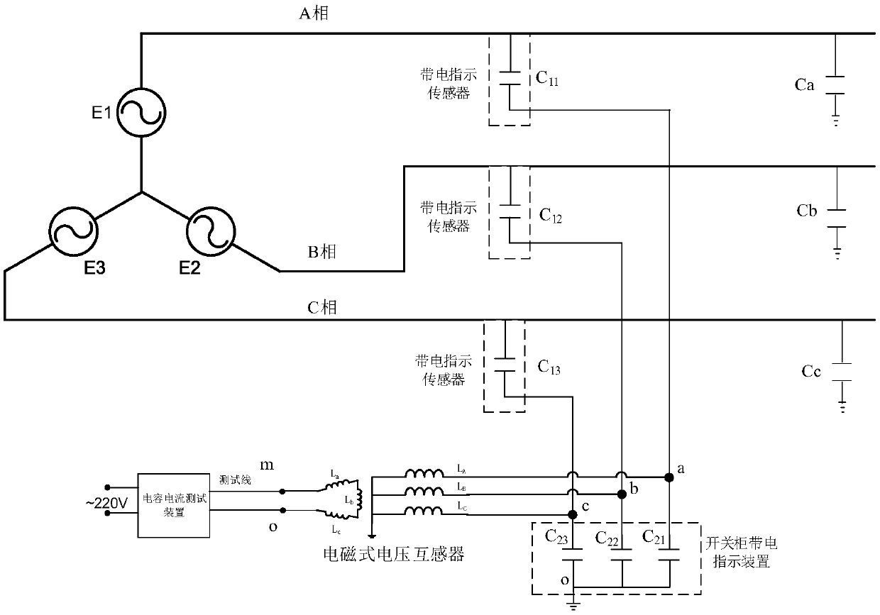
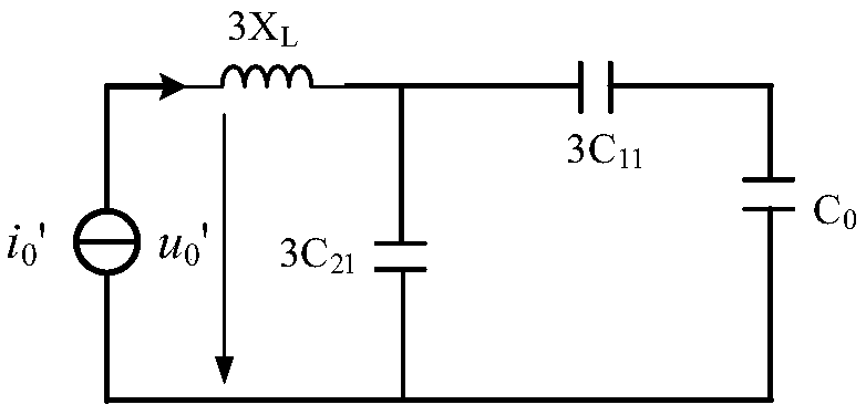
[0031] Please refer to figure 1 and 2 , which are an electrical wiring diagram of a capacitive current testing system based on a switchgear live indicator device provided in an embodiment of the present application and an electrical equivalent circuit diagram of a system-to-ground capacitance measurement. Depend on figure 1 and 2 It...


PUM


Abstract

The invention provides a capacitive current test method, device and system. The method comprises the steps that the primary side of an electromagnetic voltage transformer is electrically connected with the a-phase end, the b-phase end and the c-phase end of a switch cabinet live indication device; the high frequency voltage module of the capacitive current test device outputs the preset abnormal frequency current signal; the test module acquires the abnormal frequency voltage of the secondary side of the electromagnetic voltage transformer under the abnormal frequency current signal; and the total ground capacitance and the ground capacitive current of the isolated neutral system can be calculated according to the abnormal frequency voltage, the abnormal frequency current and the capacitance of the live indication sensor. The abnormal frequency signal is injected and measured by ingeniously using the open delta of the electromagnetic voltage transformer so as to have the characteristics of high safety, high anti-interference capacity and convenient measurement in comparison with the method of direct signal injection. The method is simple in test loop and high in safety without power outage so as to be suitable for the ungrounded system capacitive current test.

Description

technical field [0001] The present disclosure relates to the technical field of electric power systems, in particular to a method, device and system for testing capacitive current. Background technique [0002] In the neutral point ungrounded system, when the line is single-phase grounded, the current flowing through the fault point is the capacitive current generated by the line-to-ground capacitance. Most of the faults in the neutral point ungrounded system are caused by the excessive capacitive current when the line is single-phase grounded, and the arc is not easy to self-extinguish. my country's power system stipulates that when the capacitive current of the 10kV and 35kV systems is greater than 30A and 10A, an arc suppression coil should be installed to compensate the capacitive current. In order to determine the compensation capacity of the arc suppression coil, a capacitive current test should be carried out. In addition, in order to verify whether ferromagnetic res...

Claims


Application Information

Patent Timeline
IPC IPC(8): G01R31/02G01R19/00
CPCG01R19/0092G01R31/50
Inventor 刘红文王科李昊
Owner YUNNAN POWER GRID CO LTD ELECTRIC POWER RES INST
Learn More