Cooling protection device for electromechanical equipment

A technology of electromechanical equipment and protective devices, which is applied in the structural parts of electrical equipment, electrical components, cooling/ventilation/heating transformation, etc., which can solve the problems that products cannot be widely promoted, poor heat dissipation, and mechanical technology and electronic technology cannot be extensive and in-depth Development and other issues

Active Publication Date: 2018-10-12
XINXIANG POWER SUPPLY COMPANY STATE GRID HENAN ELECTRIC POWER +1
View PDF5 Cites 23 Cited by
  • Summary
  • Abstract
  • Description
  • Claims
  • Application Information

AI Technical Summary

Problems solved by technology

Since the development of electronic technology had not reached a certain level at that time, the combination of mechanical technology and electronic technology could not be widely and deeply developed, and the developed products could not be widely promoted.
[0003] Most of the existing electromechanical equipment has the problem of high internal heat and poor heat dissipation during operation

Method used


Image

  • Cooling protection device for electromechanical equipment
  • Cooling protection device for electromechanical equipment
  • Cooling protection device for electromechanical equipment

Examples


Embodiment 1

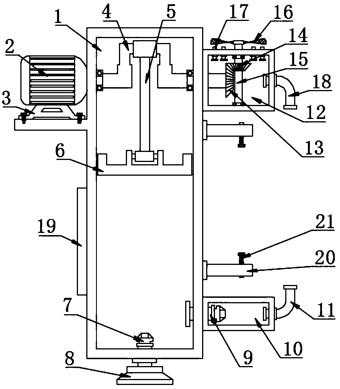
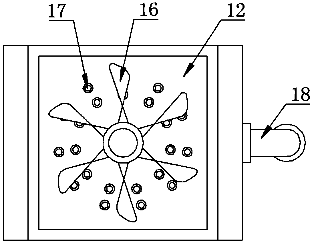
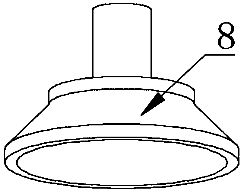
[0023] see Figure 1-3 , in an embodiment of the present invention, a heat dissipation protection device for electromechanical equipment, including a device body 1, a crankshaft 4, a suction cup 8, an air pump 12, a driven shaft 15, and an exhaust fan 16; the upper left side of the device body 1 is set The raised horizontal plate is provided with a driving motor 2 above the raised horizontal plate, and the lower part of the driving motor 2 is fixedly connected to the motor base 3, and the motor base 3 is fixedly connected to the raised horizontal plate with bolts, and the driving motor 2 is connected to the power supply and the switch by wires. The right side of the motor 2 rotates to connect the crankshaft 4, the crankshaft 4 passes through the device body 1 and is connected to the bearing in rotation, the switch is turned on so that the drive motor 2 is energized to drive the crankshaft 4 to rotate; The lower end of the connecting rod 5 is connected to the piston plate 6 by ...

Embodiment 2

[0027] see Figure 1-3 , in an embodiment of the present invention, a heat dissipation protection device for electromechanical equipment, including a device body 1, a crankshaft 4, a suction cup 8, an air pump 12, a driven shaft 15, and an exhaust fan 16; the upper left side of the device body 1 is set The raised horizontal plate is provided with a driving motor 2 above the raised horizontal plate, and the lower part of the driving motor 2 is fixedly connected to the motor base 3, and the motor base 3 is fixedly connected to the raised horizontal plate with bolts, and the driving motor 2 is connected to the power supply and the switch by wires. The right side of the motor 2 rotates to connect the crankshaft 4, the crankshaft 4 passes through the device body 1 and is connected to the bearing in rotation, the switch is turned on so that the drive motor 2 is energized to drive the crankshaft 4 to rotate; The lower end of the connecting rod 5 is connected to the piston plate 6 by ...


PUM


Abstract

The invention discloses a cooling protection device for electromechanical equipment. A middle crooked part of a crank sleeves the upper end of a connecting rod, the lower end of the connecting rod isrotatably connected with a piston plate, the edge of the piston plate is sealably and slidably connected with the inner wall of a device body, and the lower end of the device body is fixedly connectedwith a suction cup; the lower portion of the suction cup is communicated with the atmosphere, the right side of the lower portion of the device body is communicated with a second one-way valve, the second one-way valve is arranged in an air blowing cylinder, the right end of the air blowing cylinder is fixedly connected with an air inlet pipe, the lower portion of the air inlet pipe is communicated with the interior of the air blowing cylinder, and the upper end of the air inlet pipe is communicated with the interior of the electromechanical equipment. By means of the cooling protection device, through the rotary crank and the connecting rod, the piston plate is driven to move up and down along the inner wall of the device body back and forth, so that air pressure in the device body is constantly changed, and external air is sucked; through the second one-way valve, the air enters the air blowing cylinder, and is then exhausted into the electromechanical equipment through the air inlet pipe to be cooled; meanwhile, the crank drives a first bevel gear to rotate, then a second bevel gear and a driven shaft are driven to rotate, the driven shaft drives an exhaust fan to rotate to form negative pressure, so that the air in an air sucking cylinder is exhausted from a cooling pipe.

Description

technical field [0001] The invention relates to a heat dissipation protection device, in particular to a heat dissipation protection device for electromechanical equipment. Background technique [0002] The development of mechatronics can be roughly divided into three stages. The first stage was before the 1960s, and this stage is called the primary stage. During this period, people consciously or unconsciously used the preliminary achievements of electronic technology to improve the performance of mechanical products. Especially during the Second World War, the war stimulated the combination of mechanical products and electronic technology. These electromechanical combined military technologies were converted to civilian use after the war, which played a positive role in the recovery of the post-war economy. At that time, research and development were still in a state of spontaneity on the whole. Since the development of electronic technology had not reached a certain le...

Claims


Application Information

Patent Timeline
Patent Type & Authority Applications(China)
IPC IPC(8): H05K7/20
CPCH05K7/20136
Inventor 张传达季智红王孝周
Owner XINXIANG POWER SUPPLY COMPANY STATE GRID HENAN ELECTRIC POWER
Why Eureka
Try Eureka