
Self-cleaning liquid stirring device

An automatic cleaning and stirring device technology, which is applied to mixers with rotating stirring devices, mixer accessories, transportation and packaging, etc., can solve the problems of time-consuming and laborious, incomplete cleaning of the inner wall of the mixing box, etc.

Inactive Publication Date: 2018-10-16
WUHU NOKAN BIOTECH
View PDF4 Cites 0 Cited by
  • Summary
  • Abstract
  • Description
  • Claims
  • Application Information

AI Technical Summary

Problems solved by technology

[0003] As disclosed in Chinese patent 201620997850.8, a mixer with the function of automatically cleaning the mixing head includes a main control box, a hydraulic lifting motor, a speed regulating motor, a hydraulic lifting frame, a cleaning liquid tank, a water tank, a spray device, a hollow mixing head, The brush movement track, the brush, the hydraulic lifting motor, the speed regulating motor are electrically connected to the main control box, the cleaning liquid tank and the water tank are all arranged on the top of the hydraulic lifting frame, and the exits of both are equipped with The electromagnetic valve electrically connected to the main control box, the water tank and the spraying device are connected through pipelines, the moving track of the brush is fixed on the hydraulic lifting frame, and one end of the brush is electrically connected to the main control box. Drive device, the outlet of the water tank is provided with a micro booster pump electrically connected to the main control box, the hollow stirring head is provided with a heating module electrically connected to the main control box, and the inside of the brush is provided with a The shape of the hollow stirring head is similar to the half cavity. This invention can quickly and effectively remove the stains attached to the stirring head, and dry the stirring head after cleaning, which improves work efficiency and reduces labor costs. The disadvantage of this invention is that only To clean the mixing head, the cleaning of the inner wall of the mixing box has been further improved. It can only be cleaned manually, and the cleaning of the inner wall of the mixing box will be incomplete and time-consuming and laborious.

Method used


Image

  • Self-cleaning liquid stirring device
  • Self-cleaning liquid stirring device

Examples


Embodiment Construction

[0018] The following will clearly and completely describe the technical solutions in the embodiments of the present invention with reference to the accompanying drawings in the embodiments of the present invention. Obviously, the described embodiments are only some, not all, embodiments of the present invention. Based on the embodiments of the present invention, all other embodiments obtained by persons of ordinary skill in the art without making creative efforts belong to the protection scope of the present invention.

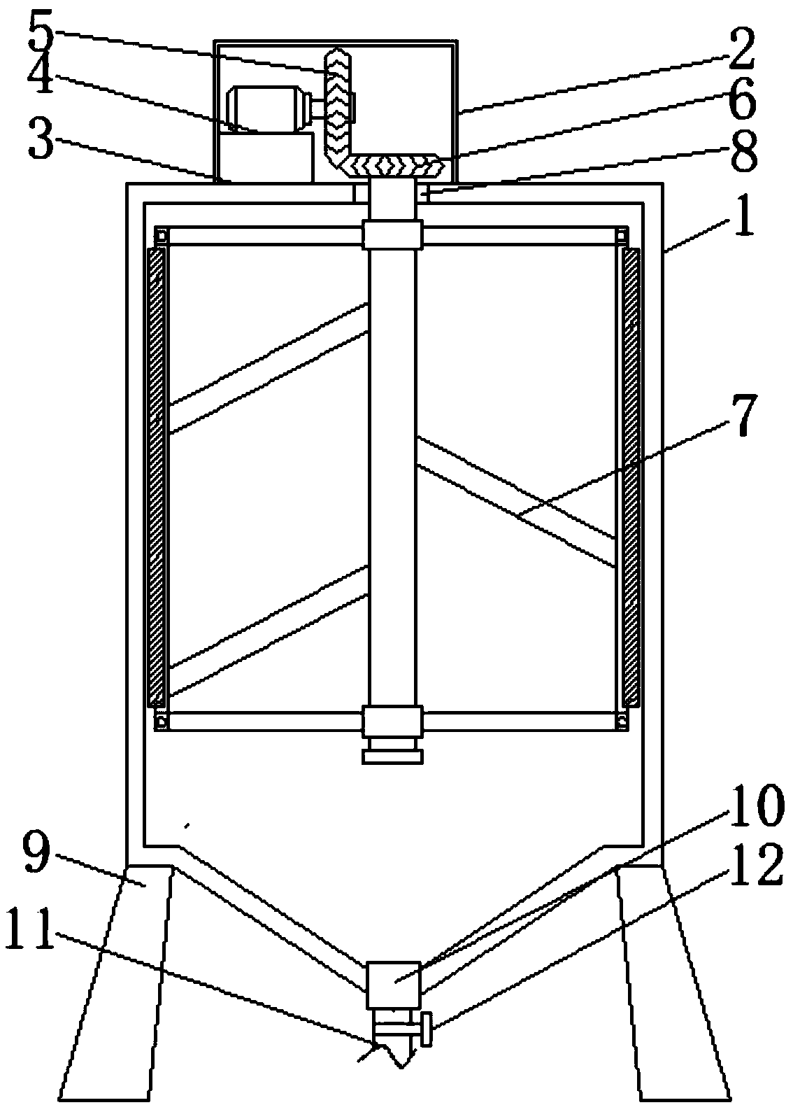
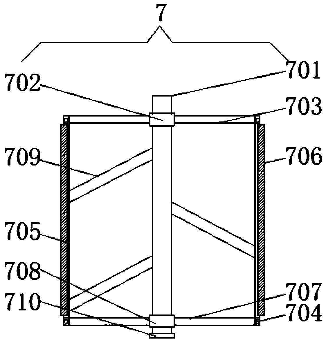
[0019] Such as Figure 1-2 As shown, the embodiment of the present invention provides a self-cleaning liquid stirring device, comprising a stirring box 1, the top of the stirring box 1 is fixedly connected with a motor box 2, and the left side of the top of the stirring box 1 is fixedly connected with a pad 3, and the pad 3 is located inside the motor box 2, and the left side of the spacer 3 is fixedly connected to the left side of the inner wall of the motor ...


PUM


Abstract

The invention provides a self-cleaning liquid stirring device and relates to the field of cleaning of biological equipment. The self-cleaning liquid stirring device comprises a stirring box, a cushionblock is fixedly connected to the left side of the top of the stirring box and is located in a motor case, the left side of the cushion block is connected to the left side of the inner wall of the motor case, a motor is fixedly connected to the top of the cushion block, a first gear is fixedly connected to the motor through a rotating shaft, the bottom of the first gear is meshed with a second gear, and a cleaning unit is fixedly connected tot the bottom of the second gear. The cleaning unit is arranged in the stirring box, a support rod is fixedly connected between a first cross rod and a second cross rod when a stirring rod is fixedly connected to the outer surface of a rotating rod, a brush plate is fixedly connected to the outer side of the support rod, the inner wall of the stirringbox is cleaned during stirring, the problem that stirring and cleaning cannot be performed simultaneously is solved, the stirring box is cleaned automatically, and timesaving and laborsaving effect isachieved.

Description

technical field [0001] The invention relates to the technical field of biological equipment cleaning, in particular to an automatic cleaning liquid stirring device. Background technique [0002] Liquid mixers, also known as liquid mixing barrels and liquid mixers, are machines used to stir liquids. Usually, we also call them vertical mixers or electric mixers. Choosing the right mixer can not only save costs, but also make your own The purpose of stirring is better met, and it is widely used in chemical, pharmaceutical, water treatment, metallurgy and food industries. Stirring of non-metallic minerals, which uses a concentration of not more than 30% (calculated by weight) and a particle size of fixed components of less than 1mm. Its form is a flat-bottomed barrel-shaped radiation circulation spiral impeller mechanical agitation. [0003] As disclosed in Chinese patent 201620997850.8, a mixer with the function of automatically cleaning the mixing head includes a main control...

Claims


Application Information

Patent Timeline
Patent Type & Authority Applications(China)
IPC IPC(8): B01F7/16B01F15/00
CPCB01F27/17B01F27/213B01F27/191B01F27/80B01F35/121
Inventor 许震
Owner WUHU NOKAN BIOTECH
Learn More