
Cutting machine for PVC plastic floor

A technology for plastic flooring and cutting machines, which is applied in metal processing and other directions, and can solve problems such as the limitation of the slotting position of the plastic floor, low work efficiency, and the inability to automatically recycle strips of plastic.

Active Publication Date: 2018-10-16
浙江奕科新材料股份有限公司
View PDF4 Cites 9 Cited by
  • Summary
  • Abstract
  • Description
  • Claims
  • Application Information

AI Technical Summary

Problems solved by technology

[0004] In order to solve the above problems, the present invention provides a cutting machine for PVC plastic floor, which can solve the existing problems of low work efficiency when slotting the plastic floor, poor effect of manual slotting on the plastic floor, and the need for manual cutting of the plastic before mining. The floor is cut, the cutting effect on the plastic floor is poor, the two sides of the plastic floor cannot be rolled when the plastic floor is grooved, the strips of plastic that have been grooved cannot be automatically recycled, and the slotting position cannot be determined when the plastic floor is grooved It can realize the functions of cutting the plastic floor before slotting, automatically slotting the plastic floor, and limiting the slotting position when the plastic floor is slotted. It has high work efficiency and automatic opening of the plastic floor. The groove effect is good, the plastic floor is automatically cut before mining, the cutting effect on the plastic floor is good, the two sides of the plastic floor can be rolled when the plastic floor is grooved, and the strips of plastic that are grooved are automatically recycled. Advantages such as limiting the slotting position when slotting the plastic floor

Method used


Image

  • Cutting machine for PVC plastic floor
  • Cutting machine for PVC plastic floor
  • Cutting machine for PVC plastic floor

Examples


Embodiment Construction

[0032] In order to make the technical means, creative features, goals and effects achieved by the present invention easy to understand, the present invention will be further described below in conjunction with specific illustrations. It should be noted that, in the case of no conflict, the embodiments in the present application and the features in the embodiments can be combined with each other.

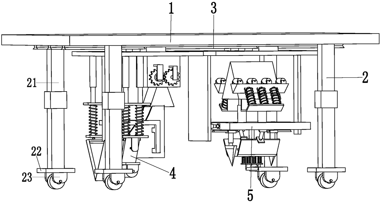
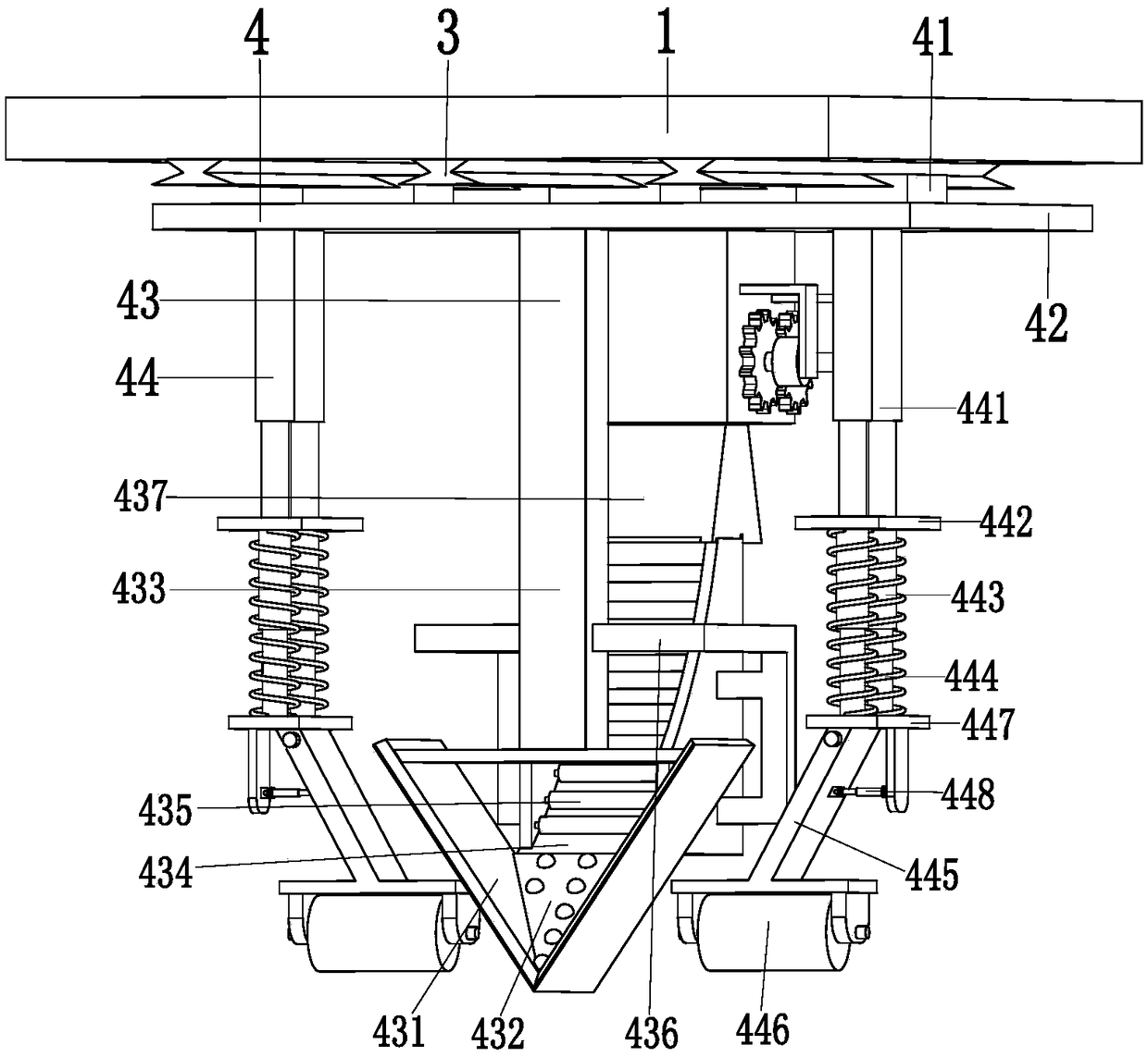
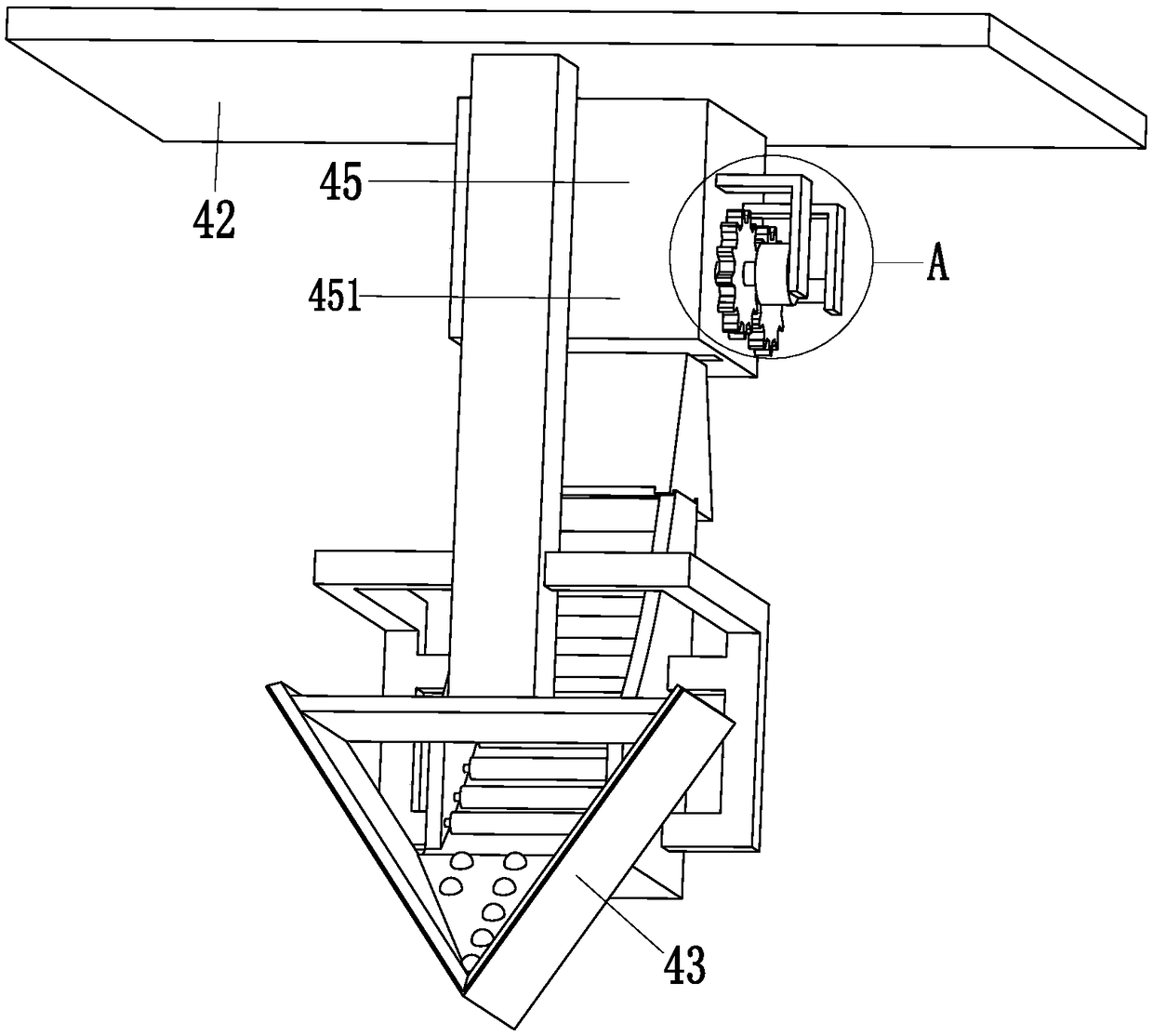
[0033] Such as Figure 1 to Figure 8 As shown, a cutting machine for PVC plastic flooring includes a supporting top plate 1, a moving mechanism 2, a moving electric slide rail 3, a grooving device 4 and a limit device 5, and the outer bottom of the supporting top plate 1 is symmetrically installed with Moving mechanism 2, moving electric slide rail 3 is installed on the middle part lower end face of supporting top plate 1, and slotting device 4 is installed on the left end of moving electric slide rail 3, and limit device 5 is installed on the right end of moving electric slide rail ...


PUM


Abstract

The invention relates to a cutting machine for a PVC plastic floor. The cutting machine comprises a supporting top plate, movable mechanisms, a movable electric sliding rail, a groove cutting device and a limiting device; the movable mechanisms are symmetrically installed on the outer side of the bottom of the supporting top plate; the movable electric sliding rail is installed on the lower end surface of the middle part of the supporting top plate; the groove cutting device is installed at the left end of the movable electric sliding rail; and the limiting device is installed at the right endof the movable electric sliding rail. The problems that the working efficiency is low when the plastic floor is slotted, the slotting effect of the plastic floor through manual work is poor, the plastic floor is required to be cut through the manual work before slotting, the cutting effect of the plastic floor is poor, the two sides of the plastic floor can not be rolled when the plastic floor isslotted, strip-shaped plastic through the slotting can not be automatically recovered, and the slotting position can not be limited when the plastic floor is slotted can be solved.

Description

technical field [0001] The invention relates to the technical field of decoration construction, in particular to a cutting machine for PVC plastic flooring. Background technique [0002] PVC plastic floor refers to the floor made of polyvinyl chloride material. Specifically, it uses polyvinyl chloride and its copolymer resin as the main raw material, and adds fillers, plasticizers, stabilizers, colorants and other auxiliary materials. , produced by coating process or calendering, extrusion or extrusion process, PVC plastic floor hereinafter referred to as plastic floor is a new type of light-weight floor decoration material that is very popular in the world today, also known as "light-weight floor material". ", has been generally recognized so far, and is widely used, such as indoor homes, hospitals, schools, office buildings, supermarkets, stadiums and other places. [0003] The paving process of the plastic floor is as follows. 1. Base treatment: remove sand, oil stains, ...

Claims


Application Information

Patent Timeline
IPC IPC(8): B26D3/06B26D11/00B26D7/01B26D7/18B26D7/02B26D7/26
CPCB26D3/065B26D7/015B26D7/018B26D7/025B26D7/18B26D7/2628B26D11/00B26D2011/005
Inventor 王兰兰
Owner 浙江奕科新材料股份有限公司
Learn More