
Rapid glass rod cutting device

A fast cutting, glass rod technology, applied in glass cutting devices, glass manufacturing equipment, manufacturing tools, etc., can solve the problems of diameter fluctuation, large impact of pneumatic devices, increase production cost, etc., and achieve the effect of short cutting cycle

Active Publication Date: 2018-10-16
HUBEI NEW HUAGUANG NEW INFORMATION MATERIALS CO LTD
View PDF8 Cites 5 Cited by
  • Summary
  • Abstract
  • Description
  • Claims
  • Application Information

AI Technical Summary

Problems solved by technology

When the device cuts off the glass rod, the cutter and the glass rod do not move relative to each other in the vertical direction, which can effectively prevent the cutter from being damaged due to longitudinal force during the high-speed rotary cutting process, but there are also disadvantages: on the one hand , the cutting device itself has a certain self-weight, and if it is suddenly added to the glass sub-rod being drawn, it will inevitably have an adverse effect on the traction force of the glass sub-rod during stretching and thus the uniformity of its diameter. The diameter of the glass sub-rod in actual production is detected. The history curve proves that with the clamping and loosening of the parallel opening and closing air claws installed on the cutting device, the diameter of the glass sub-rod fluctuates periodically accordingly, which affects the product quality; on the other hand, although the device is designed to shorten The cutting cycle adopts the "rapid pneumatic feeding system", which realizes the rapid feeding of the knife before cutting and the rapid retraction after cutting. However, due to the large number of moving components in the whole device, the impact of the pneumatic device is large when it is in motion, and it needs to be buffered. , especially due to the limited feed speed of effective cutting (as mentioned above), it usually takes more than 20 seconds to complete a cutting process. In production, it can only meet the online cutting of glass sub-rods with a breaking length greater than 600mm. For glass sub-rods In applications with shorter rod break lengths, the device will not work properly due to the frequency period required for cutting being less than the minimum duration required for the cutting process
When the glass sub-rod enters the next slicing process, the clamping length is generally about 100mm. If the down-cut length of the sub-rod exceeds this value, a second cut is required before slicing, which undoubtedly increases the production cost. , reduced production efficiency

Method used


Image

  • Rapid glass rod cutting device
  • Rapid glass rod cutting device
  • Rapid glass rod cutting device

Examples


Embodiment Construction

[0020] The principle of the present invention will be further described below with reference to the accompanying drawings.

[0021] As a subsequent processing device in the glass rod drawing process, the embodiment of the present invention needs to be used in conjunction with the glass rod drawing machine.

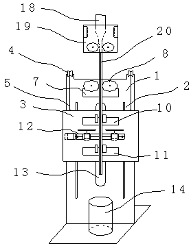
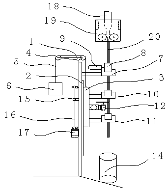
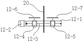
[0022] Such as figure 1 and figure 2 As shown, the glass rod rapid cutting device of the embodiment of the present invention mainly includes a frame 1, a detection unit, a lifting unit, a clamping unit, a cutting and feeding unit 12, and a control unit.

[0023] Among them, the frame 1 is a vertical plate structure, installed directly below the glass rod drawing machine 19, and the facade is strictly perpendicular to the horizontal ground and parallel to the drawing direction of the glass rod.


PUM


Abstract

The invention relates to a rapid glass rod cutting device, belongs to the technical field of production of glass rods and mainly aims to solve the problem that the diameter uniformity is affected dueto the fact that the weight of a cutting device is added to flat-drawn glass sub-rods. The device is characterized by comprising a rack, a detection unit, a lifting unit, a clamping unit, a cutting and feeding unit and a control unit, wherein the detection unit consists of a first pneumatic gripper, a rubber-covered wheel and a rotary encoder; the lifting unit consists of a sliding rail, a slidingplate, a lifting servo motor and a drive screw thereof, and the sliding plate is mounted on the sliding rail through a sliding connection piece and connected with the drive screw through a screw nutassembly; the clamping unit consists of a second pneumatic gripper and a third pneumatic gripper; the cutting and feeding unit consists of a linear guide rail, a lead screw, a feeding servo motor, a blade rotary motor and a cutting blade. The device has the characteristics that the cutting process and the drawing process are independent of each other and left and right sides are cut simultaneously, and is mainly used for rapid cutting in the continuous sub-rod drawing process of optical glass main rods.

Description

technical field [0001] The invention belongs to the technical field of glass rod production, and in particular relates to a glass rod rapid cutting device, which is used for online cutting and breaking glass sub-rods according to a set length during the drawing process of glass rods, especially optical glass rods. . Background technique [0002] With the increasing miniaturization and high performance of optical components, the market demand for small-diameter optical glass rods continues to increase. In order to improve the yield rate of products and reduce production costs, in the production practice, the method of optical fiber drawing is used for reference, and optical glass master rods with larger diameters are pre-prepared through one-time molding, and then drawn with different diameters through the drawing machine. optical glass rods. Since the drawing process of the same master rod is continuous, the optical glass sub-rods produced need to be cut online according t...

Claims


Application Information

Patent Timeline
Patent Type & Authority Applications(China)
IPC IPC(8): C03B33/06
CPCC03B33/06
Inventor 焦胜兵喻涧临李兢
Owner HUBEI NEW HUAGUANG NEW INFORMATION MATERIALS CO LTD
Learn More