Supercharge Your Innovation With Domain-Expert AI Agents!

Pneumatic structure of shuttle

A shuttle and cylinder technology, applied in the field of shuttle pneumatic structure, can solve problems such as easy problems, high maintenance cost, complex structure, etc., and achieve the effects of simple structure, beautiful appearance, reliable and flexible action

Pending Publication Date: 2018-10-16
SHAOXING HAN XIANG PRECISION MACHINERY MFG
View PDF8 Cites 0 Cited by
  • Summary
  • Abstract
  • Description
  • Claims
  • Application Information

AI Technical Summary

Problems solved by technology

[0003] The sock machine shuttle in the prior art drives the complex mechanical structure through the electromagnet to move the shuttle assembly, the structure is complex, the maintenance cost is high, and problems are prone to occur

Method used


Image

  • Pneumatic structure of shuttle
  • Pneumatic structure of shuttle
  • Pneumatic structure of shuttle

Examples


Embodiment 1

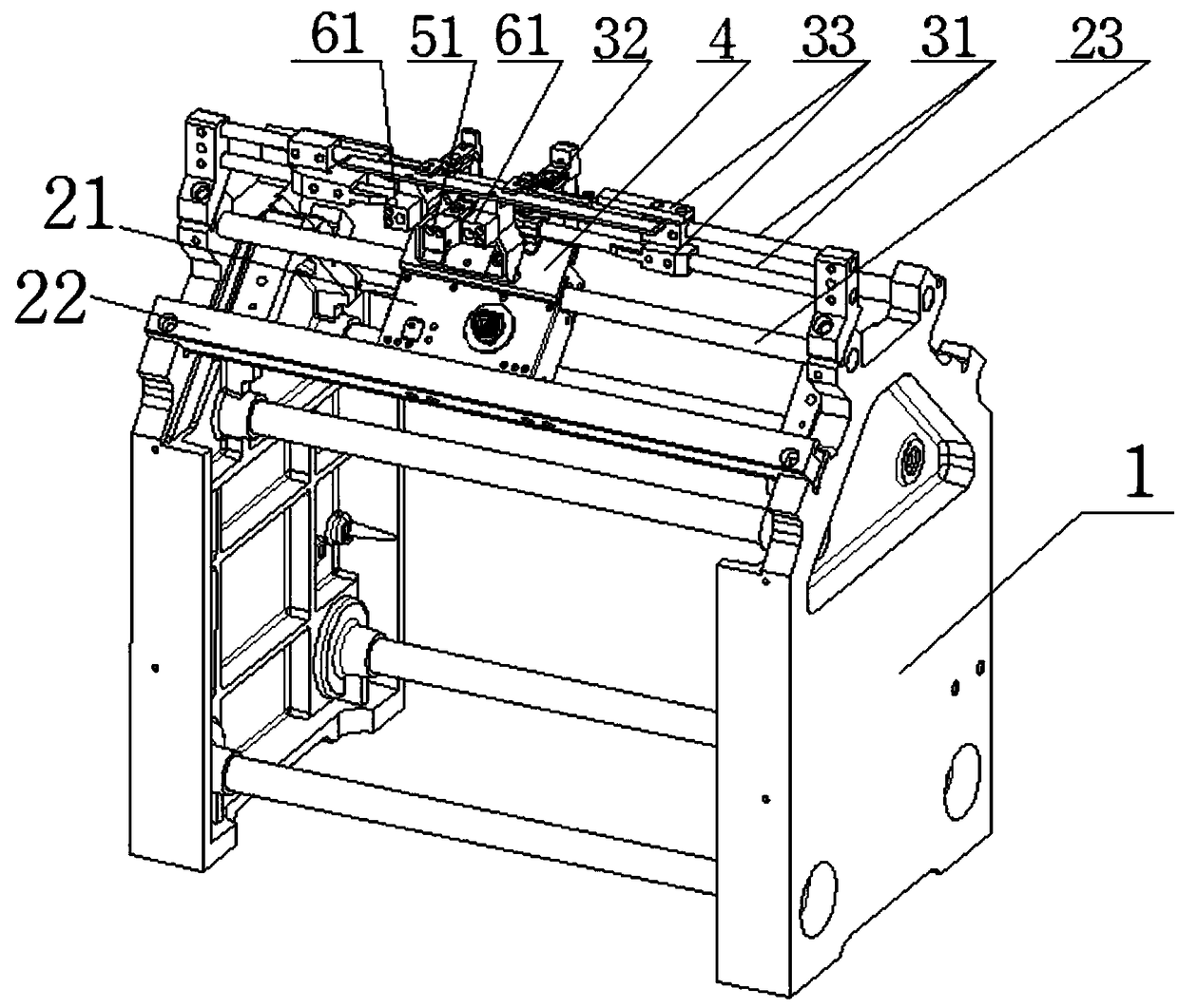
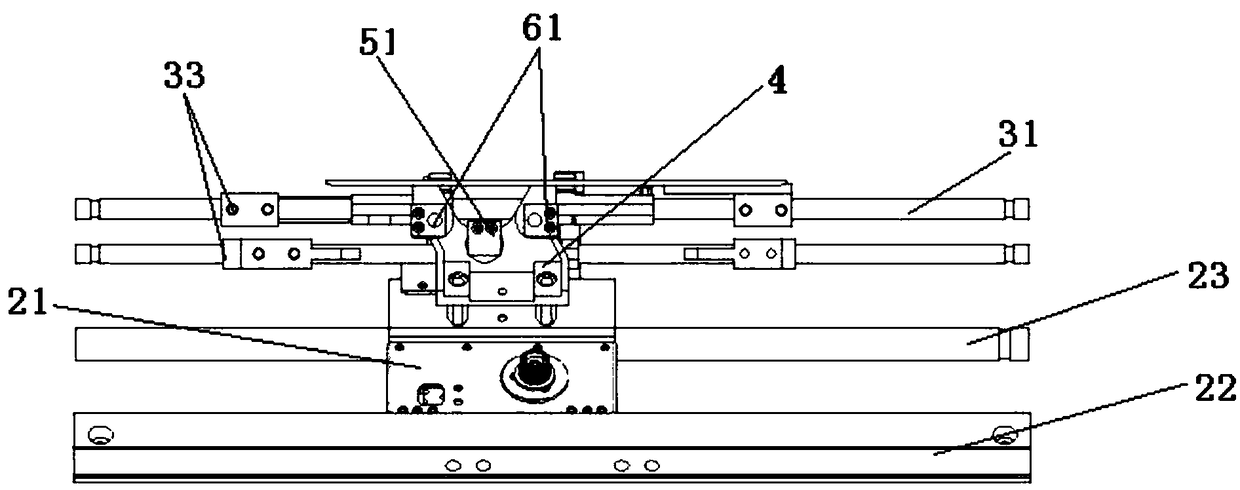
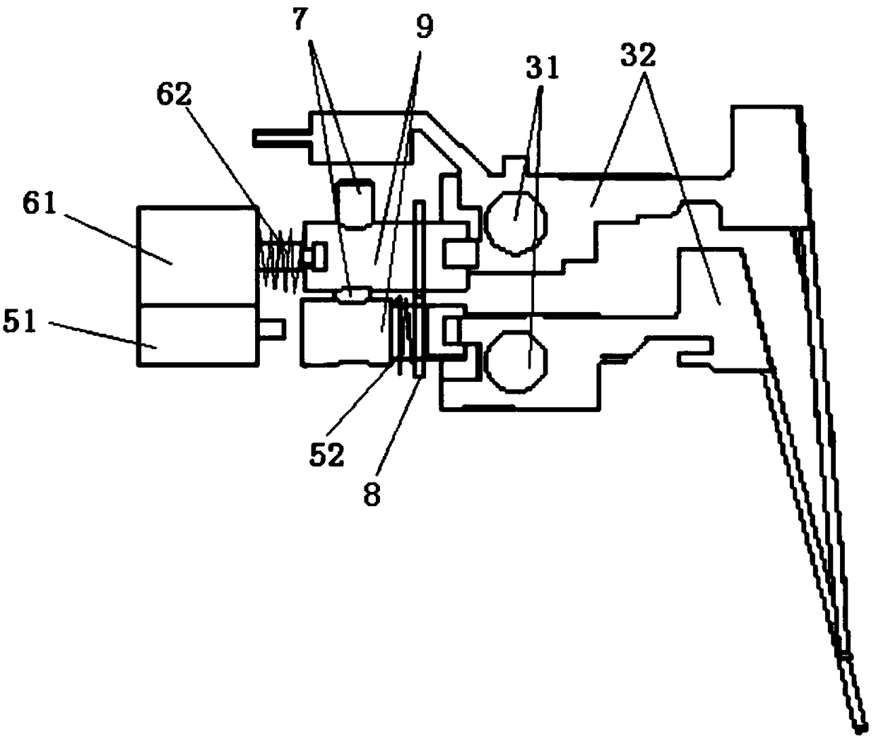
[0028] Combine below Figure 1-4 Further explanation: a shuttle pneumatic structure, including a mounting bracket 1, a cylinder (the figure shows the situation that both the pull cylinder 61 and the push cylinder 51 are used, the middle one is the push cylinder 51, and the two sides are pull cylinders 61), Shuttle driving shaft 9, head shaft frame, head shaft 23, head chute 22, shuttle assembly 32, head 21 and shuttle shaft 31, and described mounting frame 1 is provided with head shaft 23 and head chute 22 , the upper part of the machine head 21 is installed on the machine head shaft 23 through a sliding connection, the lower part of the machine head 21 is slidably connected with the machine head chute 22 through the bearing 24, and the machine head is installed on the upper part of the machine head 21 Pedestal 4, a cylinder is installed on the head spindle frame 4, a shuttle drive shaft 9 is provided on the head spindle frame 4, and the shuttle drive shaft 9 and the cylinder ...

Embodiment 2

[0039] Others are all the same as in Embodiment 1, except that there are two pulling cylinders and three pushing cylinders.

Embodiment 3

[0041] Others are all the same as in Embodiment 1, except that there are three pulling cylinders and no pushing cylinders.


PUM


Abstract

The invention relates to the field of glove making machine parts, in particular to a pneumatic structure of a shuttle. The pneumatic structure of the shuttle comprises a mounting rack, an air cylinder, a shuttle driving shaft, a handpiece shaft rack, a handpiece shaft, a handpiece sliding groove, a shuttle assembly, a handpiece and a shuttle shaft, wherein the handpiece shaft and the handpiece sliding groove are arranged on the mounting rack, the upper portion of the handpiece is slidingly connected and installed on the handpiece shaft, the lower portion of the handpiece is in sliding connection with the handpiece sliding groove through a bearing, the handpiece shaft rack is installed at the upper portion of the handpiece, the air cylinder is installed on the handpiece shaft rack, the shuttle driving shaft is arranged on the handpiece shaft rack and corresponds to the air cylinder, the shuttle shaft is arranged on the mounting rack, the shuttle assembly is mounted on the shuttle shaftand corresponds to the shuttle driving shaft. An electromagnet on an original shuttle base and a complicated mechanical structure driven by the electromagnet are omitted, and the pneumatic structure is simple and low in cost.

Description

technical field [0001] The invention relates to the field of glove machine parts, in particular to a shuttle pneumatic structure. Background technique [0002] Gloves are hand warming or labor protection articles, and are also used for decoration. Gloves are a very special thing. They were not created for practicality at the beginning, but only in modern times have they become necessary for heat preservation in cold areas, or medical antibacterial and industrial protective products. Knitted gloves are made of pure or blended yarns of various textile fibers, woven on a glove machine, and processed by sewing, such as clamping, cuffs, sewing fingertips and finger forks, etc., and then brushed or milled, heat-set Organized into products. [0003] The hosiery machine shuttle in the prior art uses electromagnets to drive a complex mechanical structure to move the shuttle assembly. The structure is complex, the maintenance cost is high, and problems are prone to occur. Contents...

Claims


Application Information

Patent Timeline
IPC IPC(8): D04B15/56
CPCD04B15/56
Inventor 李鸣黄志升宋同义
Owner SHAOXING HAN XIANG PRECISION MACHINERY MFG
Features
  • R&D
  • Intellectual Property
  • Life Sciences
  • Materials
  • Tech Scout
  • Unparalleled Data Quality
  • Higher Quality Content
  • 60% Fewer Hallucinations
Learn More