Road roller vibration electronic control system and method

An electronic control system and technology for road rollers, which are applied in the directions of roads, roads, and road repairs, can solve the problems of normal vibration, inability to set up, and vibration of road rollers in situ, and achieve the effects of reliable performance, convenient installation and maintenance, and simple structure.

Pending Publication Date: 2018-10-16
XCMG CONSTR MACHINERY
View PDF5 Cites 2 Cited by
  • Summary
  • Abstract
  • Description
  • Claims
  • Application Information

AI Technical Summary

Problems solved by technology

At present, road rollers are allowed to vibrate at engine idle speed, which will cause resonance and affect the comfort of the cab and the structure of the whole machine; road rollers are allowed to vibrate at high speeds, and high-speed vibration will affect the compaction quality of the road surface; road rollers vibrate automatically In the mode, the start and stop vibrations will alternately change when the speed boundary value is set, which will affect the compaction quality of the road surface. Affect the compaction quality of the road surface; in the automatic vibration mode, the vibration speed can only be selected and cannot be set, which cannot meet the requirements of different construction techniques; in the manual vibration mode, after the walking handle is returned to the center, the road roller will vibrate normally Press the vibration button, the whole machine will vibrate in place, which will affect the quality of the compacted road surface

Method used


Image

  • Road roller vibration electronic control system and method

Examples


Embodiment Construction

[0019] In order to make the object, technical solution and advantages of the present invention clearer, the present invention will be further described in detail below. However, it should be understood that the specific embodiments described here are only used to explain the present invention, and are not intended to limit the scope of the present invention.

[0020] Unless otherwise defined, all technical terms and scientific terms used herein have the same meaning as commonly understood by those skilled in the technical field of the present invention, and the terms used in the description of the present invention herein are only to describe specific implementations The purpose of the example is not intended to limit the present invention.

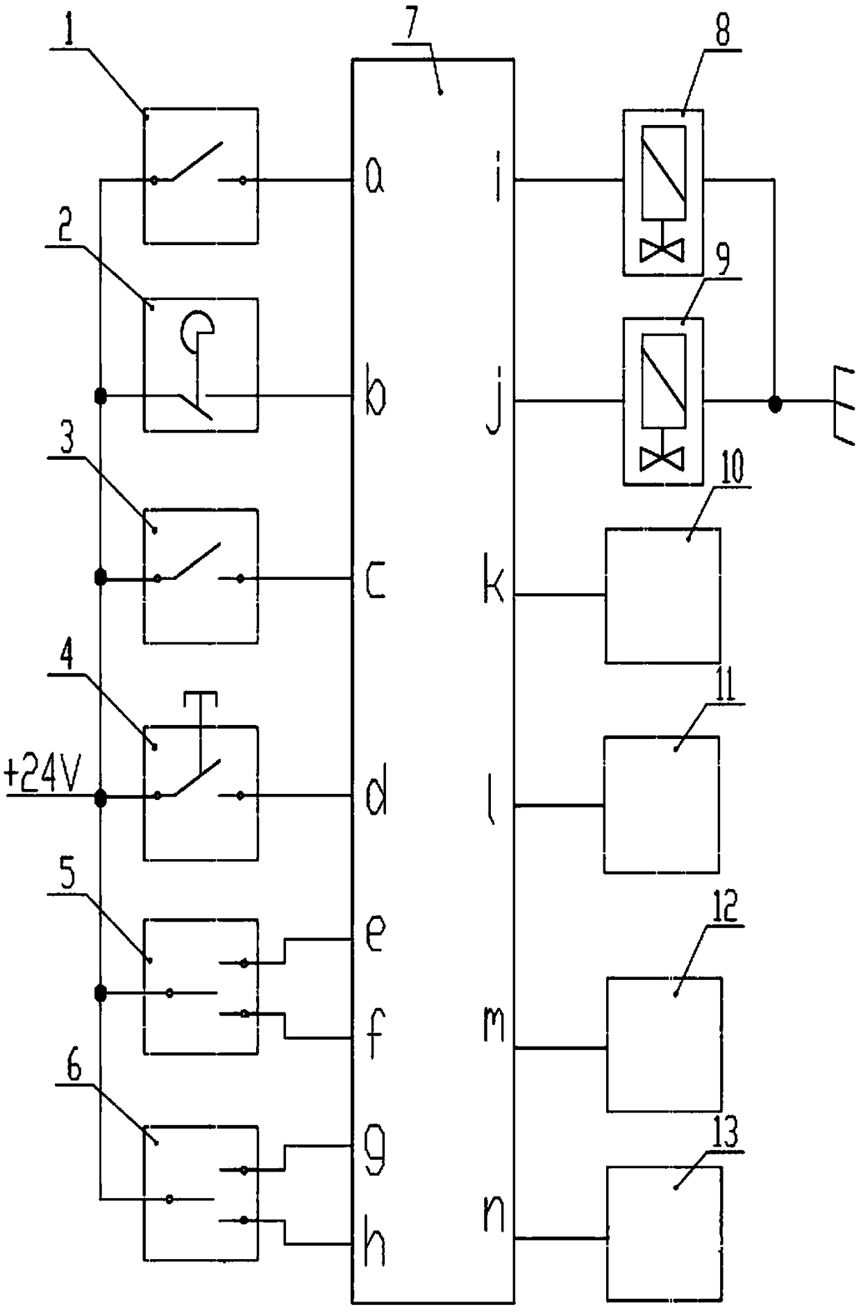
[0021] Such as figure 1 As shown, an electric vibration control system for a road roller includes an engine idle switch 1, a handle neutral switch 2, a test switch 3, a vibration button 4, an amplitude selection switch 5, a vibration mod...


PUM


Abstract

The invention discloses a road roller vibration electronic control system and method. The road roller vibration electronic control system comprises an engine idling switch, a handle meso-position switch, a test switch, a vibration button, an amplitude selection switch, a vibration mode selection switch, a controller, a high-vibration solenoid valve, a low-vibration solenoid valve, a display, a rotating speed sensor, a speed sensor and a travelling electronic control handle. According to the vibration electronic control system provided by the invention, a complete machine does not allow vibration under engine idling, and alarm popup prompt is achieved in the display; the complete machine does not allow vibration under high-speed travelling, the speed limiting value can be adjusted to meet different construction technology requirements, and alarm popup prompt is achieved in the display; under the automatic vibration mode, a speed difference value is set for vibration starting and stopping, and thus the situation that alternate transformation of vibration starting and stopping is caused by speed fluctuation, and consequently the road surface compaction quality is affected is prevented; and under the automatic vibration mode, the controller stops outputting a vibration signal at the moment of quick back pulling of the handle, and the influence of in-situ vibration caused by improper operation on the road surface compaction quality is effectively reduced.

Description

technical field [0001] The invention relates to a road roller working system and a method thereof, in particular to a road roller vibration electric control system and an electric control method thereof. Background technique [0002] Road rollers belong to the category of compaction equipment in construction machinery, and can be divided into mechanical drive, hydraulic drive and other types according to the driving principle. At present, road rollers are allowed to vibrate at engine idle speed, which will cause resonance and affect the comfort of the cab and the structure of the whole machine; road rollers are allowed to vibrate at high speeds, and high-speed vibration will affect the compaction quality of the road surface; road rollers vibrate automatically In the mode, the start and stop vibrations will alternately change when the speed boundary value is set, which will affect the compaction quality of the road surface. Affect the compaction quality of the road surface; ...

Claims


Application Information

Patent Timeline
Patent Type & Authority Applications(China)
IPC IPC(8): E01C19/28
CPCE01C19/282
Inventor 王平市杨全超周保刚杨洁
Owner XCMG CONSTR MACHINERY
Why Eureka
Try Eureka