
Blow-filling injection system

A spray system and spray head technology, used in spray devices, earthmovers/shovels, construction, etc., can solve the problems of large labor input, high pressure of spray heads, and easy wear of spray heads, so as to reduce operating time and increase Jet Amplitude, Effect of Increasing Jet Amplitude

Pending Publication Date: 2018-10-16
CCCC TDC ENVIRONMENTAL PROTECTION DREDGING
View PDF3 Cites 3 Cited by
  • Summary
  • Abstract
  • Description
  • Claims
  • Application Information

AI Technical Summary

Problems solved by technology

[0004] The mud discharge pipeline is generally connected alternately by the mud conveying steel pipe and the rubber pipe. A nozzle is installed at the end of the last mud conveying steel pipe. The nozzle is generally in the shape of a cone. The purpose of pressurizing the sand is to spray the dredged sediment to the far away area to be filled. The internal pressure of the nozzle is very high, and the inner wall of the nozzle is also easy to wear;
[0005] In the prior art, the nozzle is generally placed on the bracket or the nozzle is made into an elbow shape. The central axis of the nozzle and the horizontal plane form a certain angle. °, so that the discharged silt falls to a fixed point in a parabola. With the continuous increase of silt, a silt pile will be formed at the fixed point. When the silt pile reaches a certain height, it will affect the nozzle to continue spraying. At this time, It is necessary to stop spraying and use bulldozers to continuously move the sand in the sand pile to other areas of the field leveling project. The filling efficiency is low and the labor input is large

Method used


Image

  • Blow-filling injection system
  • Blow-filling injection system
  • Blow-filling injection system

Examples


Embodiment Construction

[0037] The principles and features of the present invention are described below in conjunction with the accompanying drawings, and the examples given are only used to explain the present invention, and are not intended to limit the scope of the present invention.

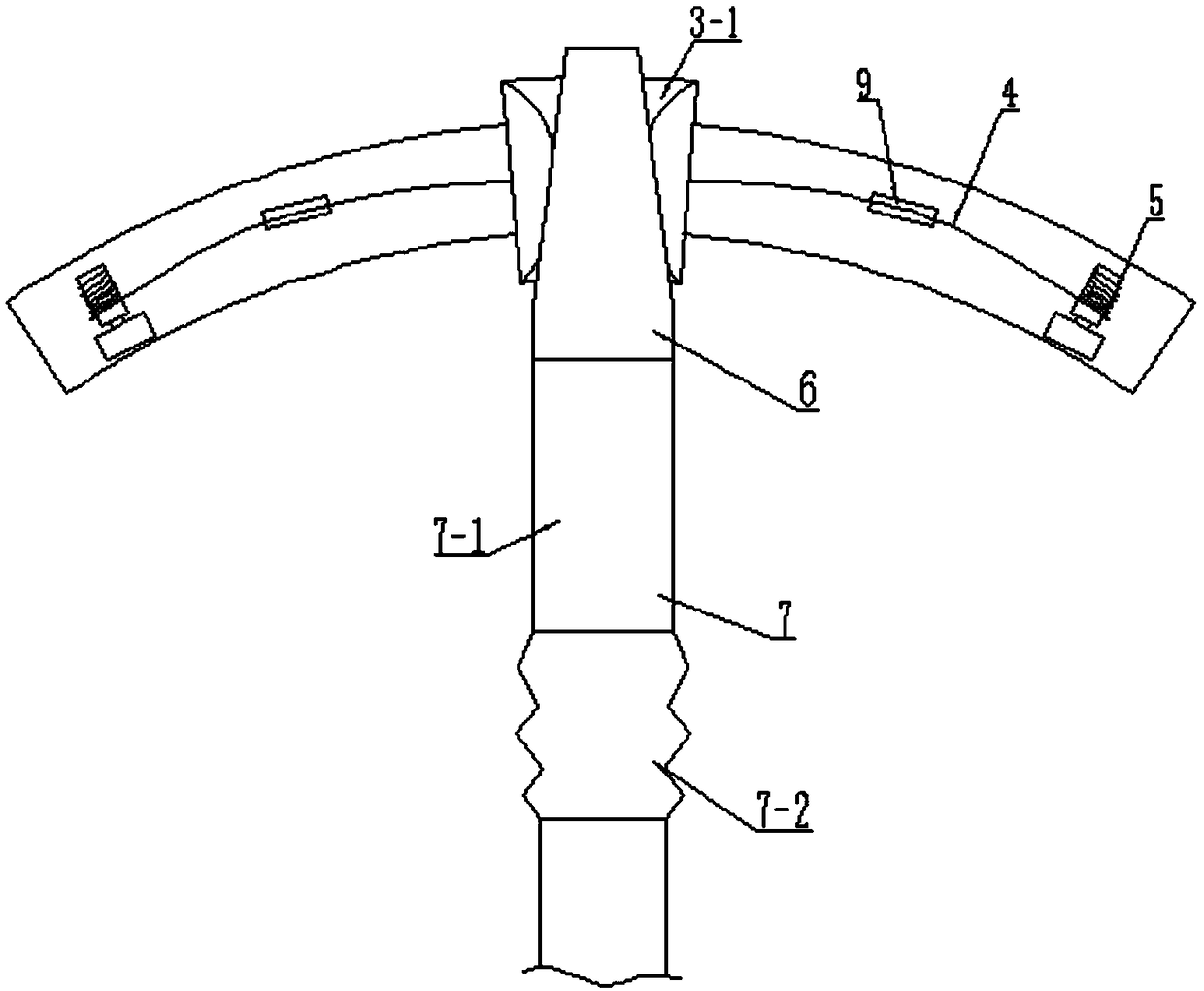
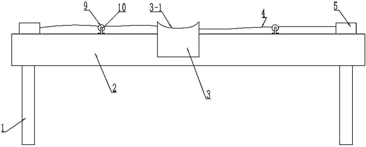
[0038] A blow-fill injection system such as Figure 1-Figure 8 As shown, it includes a nozzle guiding device, and the nozzle guiding device includes a support frame 1, a guide beam 2 arranged on the support frame 1 and a slide table 3 that can slide along the guide beam 2, and the guide beam 2 The two ends are respectively provided with a rope winding mechanism 5, and the rope winding mechanisms 5 at both ends work alternately. On the slide table 3, the guide beam and the slide table are arc-shaped.

[0039] The guide beam 2 is an arc-shaped I-steel, that is, the I-steel is bent into an arc-line shape, and the two sides of the lower part of the slide table are slidably connected to the guide beam by rollers.

[00...


PUM


Abstract

The invention relates to a blow-filling injection system. The blow-filling injection system comprises a mud discharge tube and a spray head which is arranged at a discharge end of the mud discharge tube, and further comprises a spray head guide device, wherein a spray head is fixedly arranged on the guide device; the guide device can drive the spray head to move to form an arc-shaped silt pile, sothat an injection area is greatly increased, operation time of an earth remover is reduced, and working efficiency is improved; the spray head comprises a spray head body which is in the shape of a cone; the diameter of a nozzle of the spray head body is smaller than that of an inlet; the rear end of the spray head body is equipped with a guide mechanism; the guide mechanism comprises a guide ring, a ring-shaped gas cavity and a plurality of gas-flow holes which are uniformly distributed in an annular mode; the guide ring is detachably arranged on the inner wall of the rear end of the spray head body; the guide ring is positioned at gas outlets of the gas-flow holes, so that gas flows in a spray-out direction of the spray head body; the ring-shaped gas cavity covers gas inlets of the gas-flow holes; and the ring-shaped gas cavity communicates with the gas inlets.

Description

technical field [0001] The invention relates to a dredging and filling injection system, which belongs to the technical field of dredging and filling. Background technique [0002] With the development of ports, waterways, farmland water conservancy and coastal cities, the field of dredging operations has also been extended to a large extent. From the traditional dredging and maintenance of port waterways, river and lake governance and construction of water conservancy facilities, it has successively expanded to farmland water conservancy and reservoirs. Construction and maintenance, national defense engineering construction, environmental protection dredging, land reclamation and other fields. [0003] The dredging and reclamation project refers to the operation of transporting the sediment dredged by the dredger to the designated place through the dredging pipeline for filling. According to different functions, dredging filling can be divided into two categories, one is s...

Claims


Application Information

Patent Timeline
Patent Type & Authority Applications(China)
IPC IPC(8): E02F7/00B05B15/68B05B12/18
CPCE02F7/00B05B12/18B05B15/68
Inventor 高子双刘杰章王建军徐鹏远
Owner CCCC TDC ENVIRONMENTAL PROTECTION DREDGING
Learn More