Tool type concrete composite slab cast-in-situ connecting section formwork supporting device

A formwork support and concrete technology, which is applied in the field preparation of formwork/formwork/work frame, building components, construction, etc., can solve the problems of formwork installation accuracy and installation quality, mutual interference of supports, large amount of support materials, etc. problems, to achieve the effect of facilitating construction operations, high installation accuracy, and increased construction space

Pending Publication Date: 2018-10-16
HARBIN UNIV
View PDF0 Cites 7 Cited by
  • Summary
  • Abstract
  • Description
  • Claims
  • Application Information

AI Technical Summary

Problems solved by technology

[0015] The present invention aims to solve the problem that the existing concrete laminated floor slabs are connected by hanging formwork or traditional full hall support, and there is mutual interference between the formwork support of the connecting section and the support of the prefabricated part of the laminated slab, the large amount of support material, the installation accuracy of the formwork and the installation The quality is not easy to guarantee, and a tool-type concrete composite slab cast-in-place connection section formwork support device is provided

Method used


Image

  • Tool type concrete composite slab cast-in-situ connecting section formwork supporting device
  • Tool type concrete composite slab cast-in-situ connecting section formwork supporting device
  • Tool type concrete composite slab cast-in-situ connecting section formwork supporting device

Examples


specific Embodiment approach 1

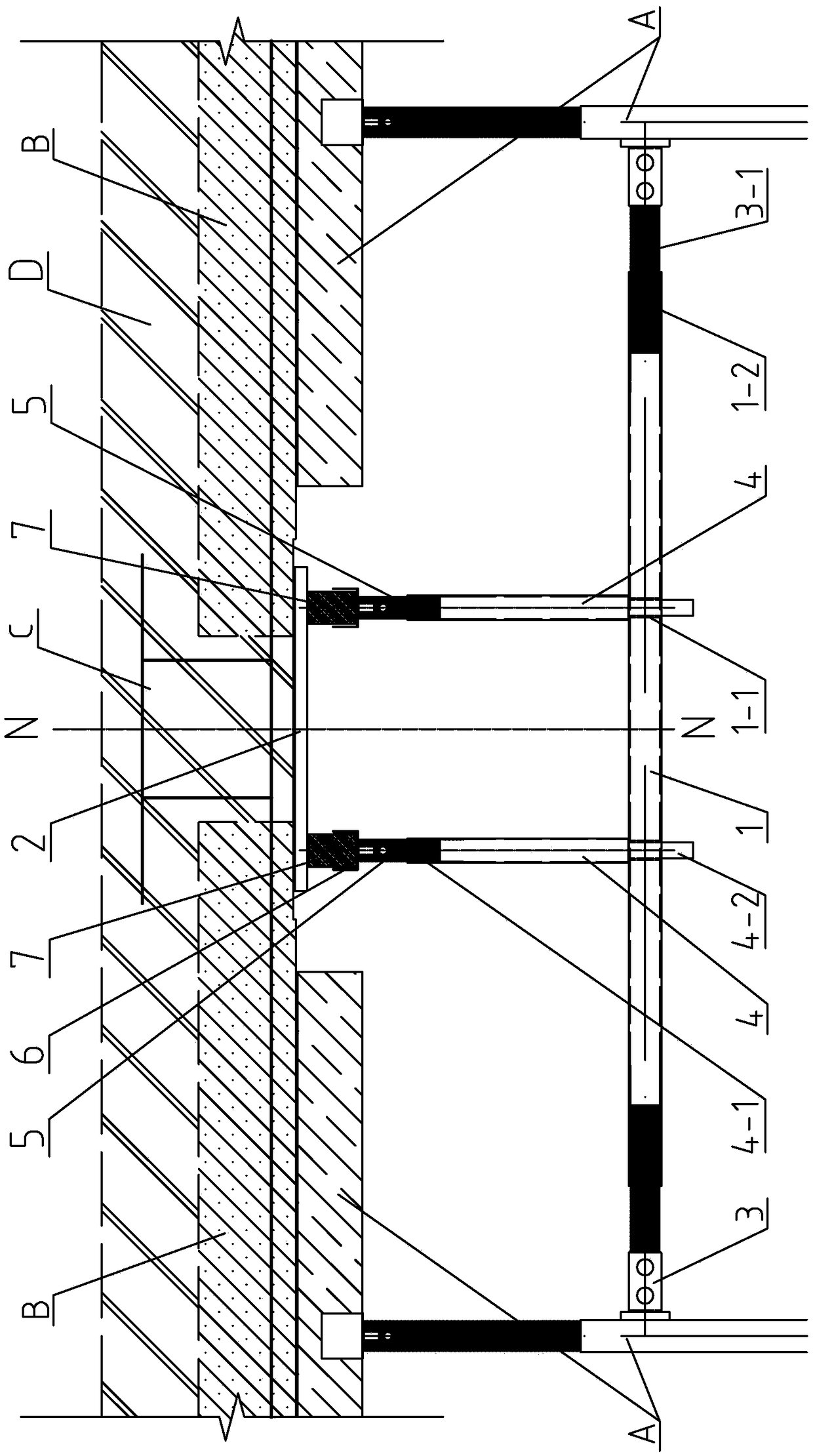
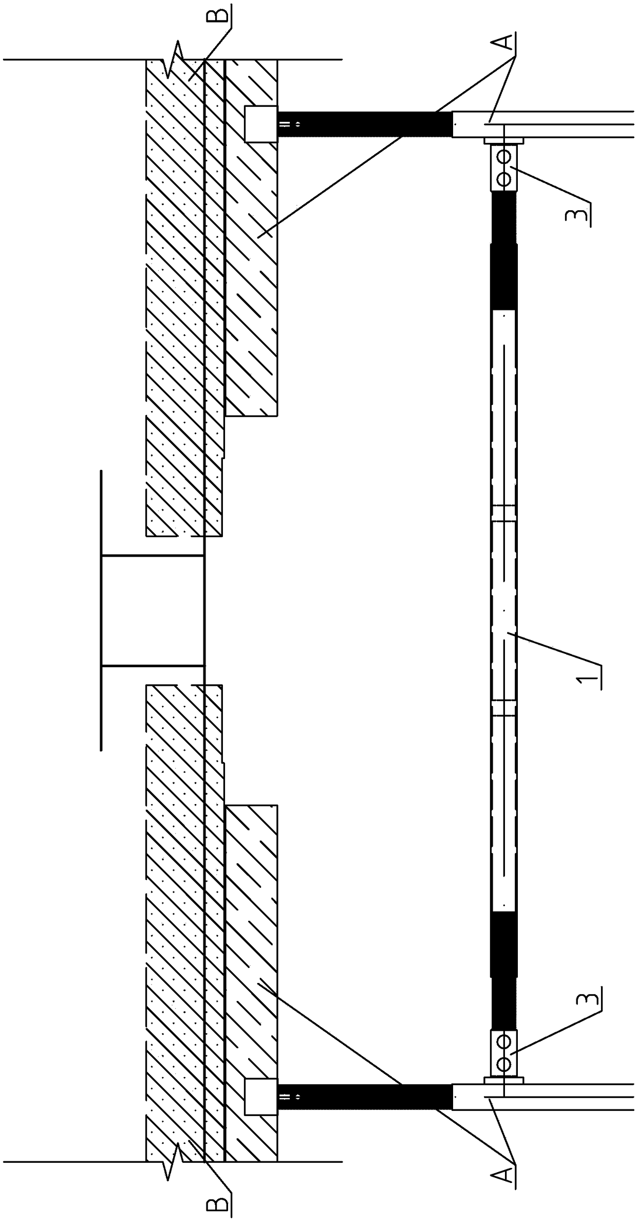
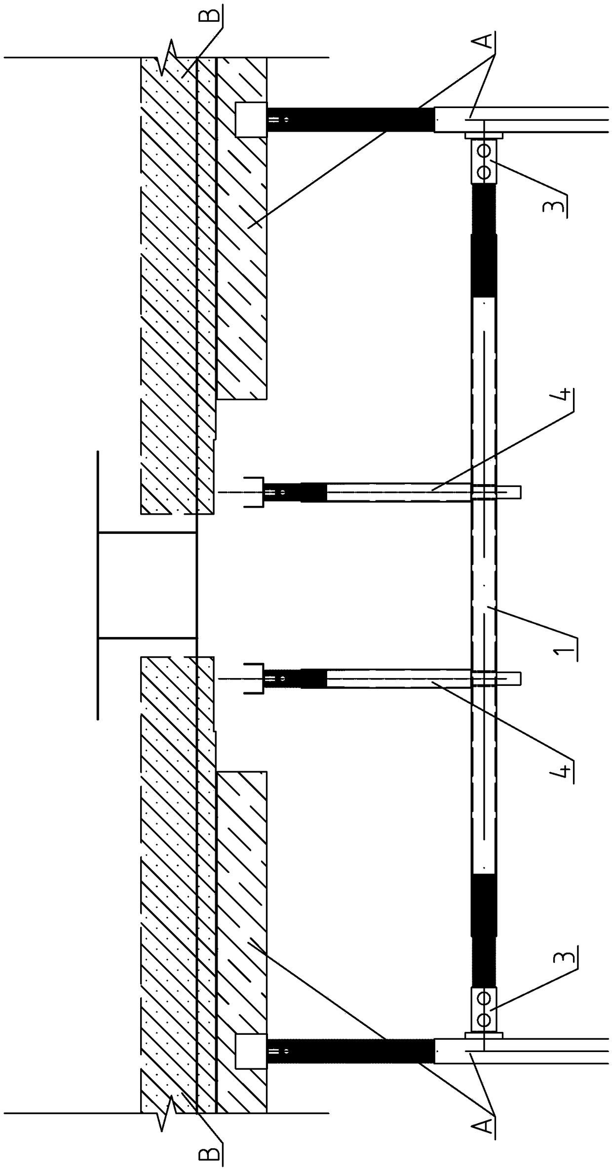
[0028] Specific implementation mode one: combine figure 1 Describe this embodiment, this embodiment includes a support beam 1, a bottom formwork 2, two horizontal adjustment members 3, two support columns 4, two vertical adjustment members 5, two U-shaped brackets 6 and two formwork holders Beam 7;

[0029] The middle part of the support beam 1 is provided with two support column jacks 1-1, and the two lateral adjustment members 3 are symmetrically arranged at both ends of the support beam 1, and the lateral adjustment member 3 is threadedly connected with the support beam 1, and the two support columns 4 corresponds to the two support column jacks 1-1 one by one, and the support column 4 is plugged with the support beam 1, and the upper end of each support column is threaded to a vertical adjustment piece 5, and each vertical adjustment piece 5 The upper end is screwed to a U-shaped bracket 6, and each U-shaped bracket 6 is equipped with a template joist 7, and the bottom te...


PUM


Abstract

The invention discloses a tool type concrete composite slab cast-in-situ connecting section formwork supporting device. The tool type concrete composite slab cast-in-situ connecting section formwork supporting device solves the problem that existing concrete composite slab cast-in-situ connection adopts a hanging formwork or a traditional full-hall support method and the problems that connection section formwork support and prefabricated part support interfere with each other, supporting materials are large in dosage and the mounting accuracy and installation quality of the formwork are difficult to guarantee exist. Two supporting stand column inserting holes are formed in the middle portion of a supporting cross beam, two transverse adjusting pieces are symmetrically arranged at the two ends of the supporting cross beam, the transverse adjusting pieces are connected with the supporting cross beam in a threaded mode, two supporting stand columns correspond to the two supporting stand column inserting holes in a one-to-one mode, and the supporting stand columns are connected with the supporting cross beam in an inserting mode. Vertical adjusting pieces are connected to the upper ends of the supporting stand columns in a threaded mode, U-shaped brackets are connected to the upper ends of the vertical adjusting pieces in a threaded mode, the U-shaped brackets are internally provided with formwork supporting beams, and a bottom formwork is arranged above the two formwork supporting beams. The tool type concrete composite slab cast-in-situ connecting section formwork supportingdevice is used in the construction of fabricated composite concrete floor.

Description

technical field [0001] The invention relates to the technical field of building construction, in particular to a formwork support device for a tool-type concrete composite slab cast-in-place connection section. Background technique [0002] The concrete laminated floor is different from the fully cast-in-place concrete floor. The bottom is prefabricated, and the upper part is laid with pipelines and cast-in-place laminated concrete forms the overall floor. [0003] During installation and construction, the prefabricated part is used as the base form of the upper cast-in-place part, and it is not necessary to set up full support and formwork like the full cast-in-place concrete floor slab, only the support is sufficient. However, the prefabricated part of the laminated slab is restricted by factors such as transportation conditions and component stiffness during transportation and hoisting. Therefore, the formwork support system of the cast-in-place connection section of the...

Claims


Application Information

Patent Timeline
Patent Type & Authority Applications(China)
IPC IPC(8): E04G11/50
CPCE04G11/50
Inventor 张新全解海杨志辉常继峰李琳
Owner HARBIN UNIV
Why Eureka
Try Eureka