Multifunctional drying device

A drying device and multi-functional technology, which is applied in the direction of drying gas arrangement, combined device, drying solid materials, etc., can solve the problems of uneven experience of the staff, affecting the service life of mechanical equipment, and harming the health of operators, so as to achieve reasonable design, The effect of maintaining integrity and convenient operation

Active Publication Date: 2018-10-16
岳阳市屈原管理区屈原茶业有限公司
View PDF7 Cites 6 Cited by
  • Summary
  • Abstract
  • Description
  • Claims
  • Application Information

AI Technical Summary

Problems solved by technology

Traditional drying uses a coal-fired boiler as a heat source, uses a combustion-supporting fan to control the firepower of the boiler, and uses a heating fan to blow the hot air in the boiler to the dryer. In the actual operation process, since the material is accumulated in the material dryer Yes, the material is prone to uneven heating
Therefore, it is necessary for the operator to constantly turn over the material during the drying process and observe the drying degree of the material. It all depends on the personal experience of the staff. This method has high technical requirements for the staff and requires more experience. The drying process needs to be tracked throughout the process. The labor intensity of the workers is high, time-consuming and labor-intensive, and the experience of the staff is uneven. It is difficult to control the quality of the materials produced.
Moreover, during the turning process of materials, a large amount of broken materials and dust will be generated. These dusts will be scattered in the air and accumulated on the mechanical equipment, causing harm to the health of the operators and affecting the service life of the mechanical equipment.

Method used


Image

  • Multifunctional drying device
  • Multifunctional drying device
  • Multifunctional drying device

Examples


Embodiment 1

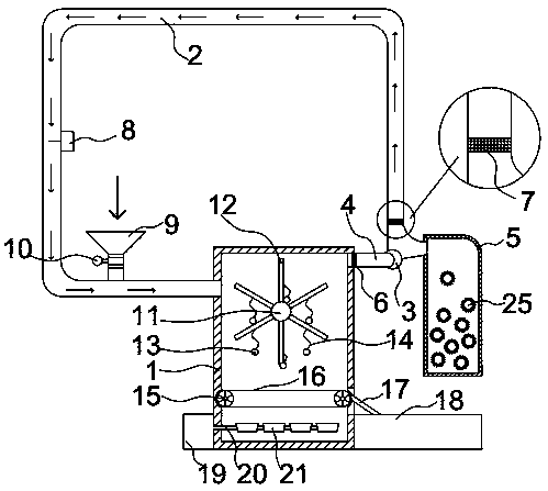
[0023] Such as figure 1 As shown, the multifunctional drying device includes a drying chamber 1, which is connected with a circulating air duct 2, and the upper feeding port of one side of the drying chamber 1 is connected with the air outlet of the circulating air duct 2, and the other side The upper part is connected with the circulation fan 3 through the branch pipe 4, the circulation air pipe 2 is provided with a feed hopper 9, the interior of the drying chamber 1 is provided with a rotating body and a transport device from top to bottom, and a discharge plate 17 is provided under the end of the transport device , the discharge plate 17 is fixedly connected to the bottom of the material collection box 18, the side wall of the connection between the circulating air duct 2 and the circulating fan 3 is provided with a dust removal chamber 5, and the interior of the dust removal chamber 5 is provided with an adsorption ball 25, and the material surface is cleaned by circulating...

Embodiment 2

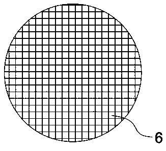
[0025] Such as Figure 1-2 As shown, the optimization scheme of this embodiment on the basis of Embodiment 1 is: a pressure sensor 8 is provided in the circulating air duct 2, and the pressure sensor 8 is in the circulating air duct 2 far away from the feed hopper 9 and the drying chamber 1, The friction and collision of the material on the pressure sensor 8 can be avoided. The speed of the circulating fan 3 can be dynamically controlled according to the feedback data of the pressure sensor 8. The connection between the branch pipe 4 and the drying chamber 1 is provided with a slag filtering net 6, and the slag filtering net 6 is preferred. The mesh size of the slag filter 6 can effectively prevent materials from entering the branch pipe 4, while smaller broken materials and dust can penetrate the slag filter 6 and be blown into the branch pipe 4. The dust removal chamber 5 and the circulating air duct 2 There is a dust filtering net 7 at the connection of the dust filtering n...

Embodiment 3

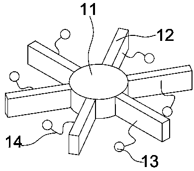
[0027] Such as Figure 3-4As shown, the optimization scheme of this embodiment on the basis of Embodiment 1 is: the rotating body includes a rotating shaft 11 and a rotating plate 12, an elastic rope 14 is connected to the rotating plate 12, and the elastic rope 14 is located at the center of the surface of the rotating plate 12 position, the longest distance of the stretched elastic cord 14 is no more than the distance between the centers of the two rotating plates 12, preventing the elastic cord 14 from becoming a mess due to the excessive length of the elastic cord 14, the end of the elastic cord 14 The rubber ball 13 is connected, and the rotating plate 12 is driven to rotate with the air circulation of the circulating air pipe 2, so that the materials entering the drying chamber 1 are stirred, and the uniformity of material drying is improved. The material of the rotating plate 12 is iron, and the rotating plate 12 The elastic rope 14 on the plate is pulled by the rotatin...


PUM


Abstract

The invention provides a multifunctional drying device. The multifunctional drying device comprises a drying room, wherein the drying room is connected with a circulating air tube; a charge hole in the upper part of one side of the drying room communicates with an air outlet of the circulating air tube; the upper part of the other side of the drying room is connected with a circulating fan througha supporting tube; a charge hopper is arranged on the circulating air tube; a rotary body and a transport device are arranged inside the drying room from top to bottom; a discharge plate is arrangedbelow the end part of the transport device; the discharge plate is fixedly connected with the bottom of a material collecting box; a dust removal room is arranged on the side wall of a joint of the circulating air tube and the circulating fan; and an adsorbing ball is arranged inside the dust removal room. A circulating air flow way is adopted for preliminarily drying water on the surfaces of materials, and the materials uniformly diffuse and move under action of air flow, are directly blown into the drying room, and are not in contact with the inner wall of the circulating air tube, so that material breakage is reduced, and integrity of the materials is kept. The device does not need manual intervention throughout the process, and uniformly heat the materials, so that a material breakingrate can be reduced, and the quality guarantee period of the materials is prolonged, and therefore, the multifunctional drying device is suitable for large-scale popularization.

Description

technical field [0001] The invention belongs to the technical field of drying equipment, and in particular relates to a multifunctional drying device. Background technique [0002] Drying and aromatherapy is an important operation process in material production. It is generally completed in a material dryer, and the material is dried with hot air. The drying stage is very critical to the quality of the material, and this stage directly determines the taste of the material. Traditional drying uses a coal-fired boiler as a heat source, uses a combustion-supporting fan to control the firepower of the boiler, and uses a heating fan to blow the hot air in the boiler to the dryer. In the actual operation process, since the material is accumulated in the material dryer Yes, the material is prone to uneven heating. Therefore, it is necessary for the operator to constantly turn over the material during the drying process and observe the drying degree of the material. It all depends...

Claims


Application Information

Patent Timeline
Patent Type & Authority Applications(China)
IPC IPC(8): F26B15/18F26B21/04F26B21/10F26B25/00B01D50/00
CPCB01D50/00F26B15/18F26B21/04F26B21/10F26B25/00
Inventor 张媛媛
Owner 岳阳市屈原管理区屈原茶业有限公司
Why Eureka
Try Eureka