
A device and method for measuring the release performance of concrete with a pressure rod

A technology of demoulding performance and concrete is applied in the field of pressure rod-type devices for measuring the demoulding performance of concrete, which can solve the problems of time-consuming and laborious operation, complicated equipment cost, inaccuracy, etc. effect of difficulty

Active Publication Date: 2020-06-26
HARBIN INST OF TECH
View PDF9 Cites 0 Cited by
  • Summary
  • Abstract
  • Description
  • Claims
  • Application Information

AI Technical Summary

Problems solved by technology

[0006] The purpose of the present invention is to provide a device and method for measuring the demoulding performance of concrete with a pressure rod, so as to solve the problems of inaccuracy, time-consuming and laborious operation, complicated equipment and high cost in the existing evaluation method of concrete demoulding performance

Method used


Image

  • A device and method for measuring the release performance of concrete with a pressure rod
  • A device and method for measuring the release performance of concrete with a pressure rod
  • A device and method for measuring the release performance of concrete with a pressure rod

Examples


specific Embodiment approach 1

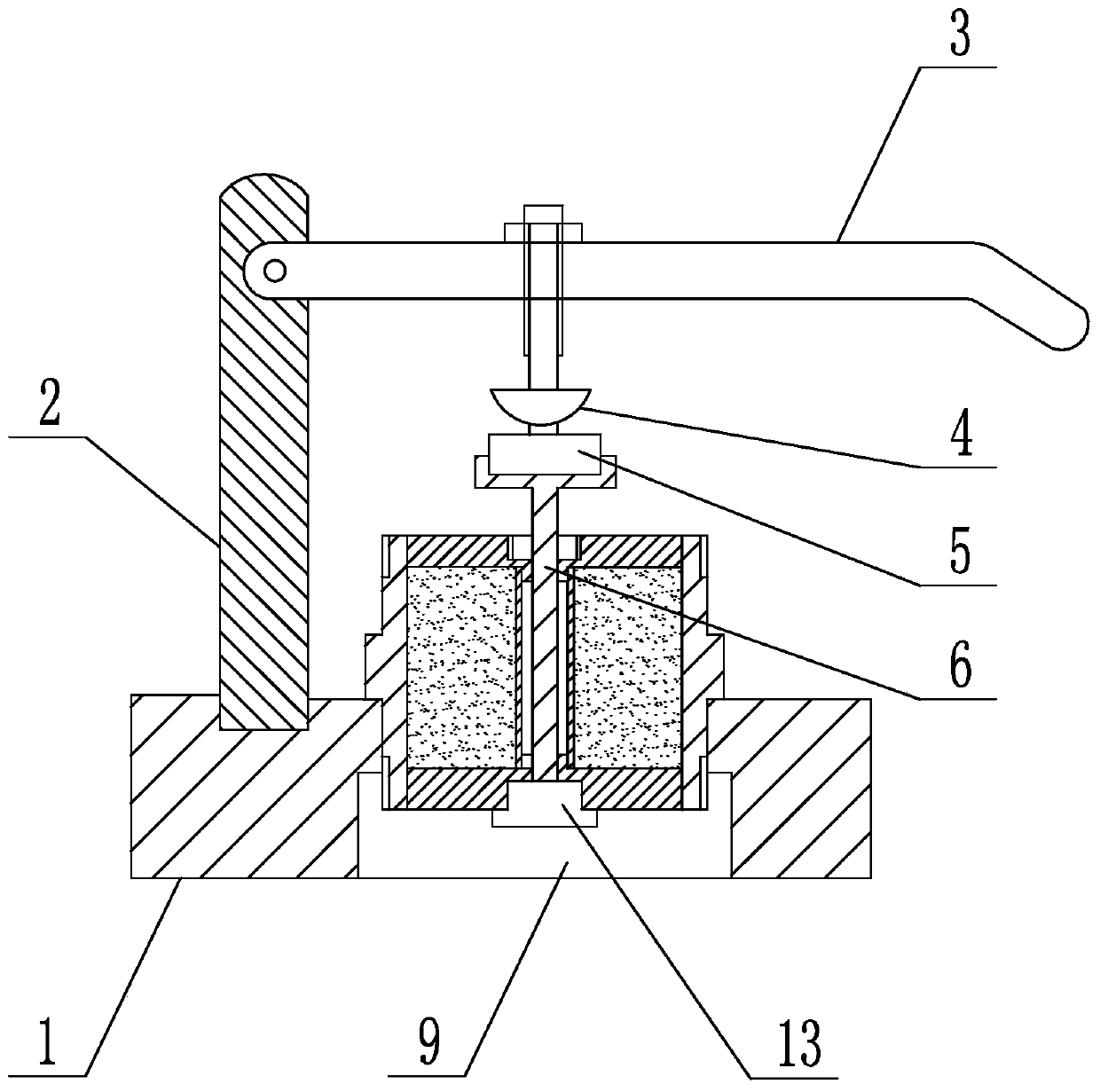
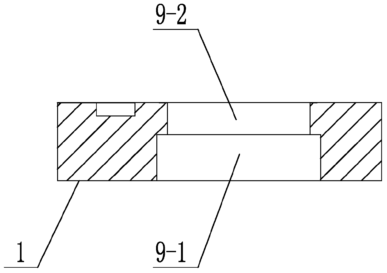
[0026] Specific implementation mode one: combine figure 1 , figure 2 , image 3 and Figure 4 Describe this embodiment, this embodiment comprises base 1, column 2, pressure rod 3, pressure member 4, pressure sensor 5, dowel 6, screw plug 13 and concrete mould, described base 1 is horizontally arranged, and column 2 is vertical It is directly arranged on the base 1 and its lower end is fixedly connected with the base 1. The base 1 is processed with a mounting hole 9 matching the concrete mold. The concrete mold includes an outer casing 8-1, an upper pressing plate 8-2, and a lower pressing plate 8-3. , the inner sleeve 8-4, the upper cover 8-5 and the lower cover 8-6, the outer wall of the outer sleeve 8-1 is provided with a shoulder 10 matched with the mounting hole 9, and the outer sleeve 8-1 passes through the shoulder 10 Clipped on the installation hole 9 of the base 1, the inner casing 8-4 is inside the outer casing 8-1 and the two are arranged coaxially, and concrete ...

specific Embodiment approach 2

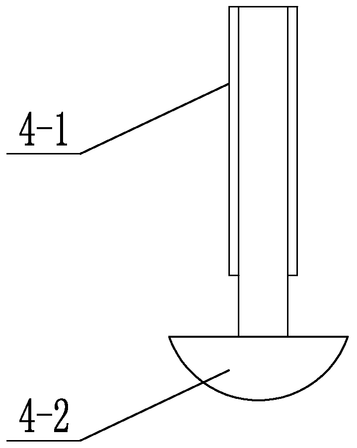
[0030] Embodiment 2: This embodiment is a further limitation of Embodiment 1. The pressure member 4 includes a connecting rod 4-1 and an arc cover 4-2. One end of the connecting rod 4-1 is detachably connected to the pressing rod 3. , the other end of the connecting rod 4-1 is provided with an arc cover 4-2, and the arc-shaped end of the arc cover 4-2 is bent toward the depression bar. The pressure member 4 is arranged as an arc-shaped screw to ensure that the pressure member 4 is always in good contact with the pressure sensor 5 and exerts force downward in the vertical direction when the pressure rod 3 is under force.

specific Embodiment approach 3

[0031] Embodiment 3: This embodiment is a further limitation of Embodiment 1 or 2. The upper platen 8-2 is processed with a first through hole 11 along its thickness direction, and the inner wall of the first through hole 11 is processed with a first internal thread. The lower pressing plate 8-3 is processed with a second through hole 12 along its thickness direction, and the inner wall of the second through hole 12 is processed with a second internal thread, and the outer wall of the plug 13 is processed with a first internal thread and a second internal thread respectively. The screw thread matches the external thread, and the screw plug 13 is detachably connected to the second through hole 12. When the dowel rod 6 passes through the first through hole 11, the upper end of the screw plug 13 is closely attached to the lower end of the dowel rod 6. .


PUM

PropertyMeasurementUnit
heightaaaaaaaaaa

Abstract

The utility model relates to a pressure bar type device for measuring the release performance of concrete. The existing methods for evaluating the release performance of concrete have the problems of inaccuracy, cumbersome and time-consuming steps in the operation process, complex equipment and high cost. The outer casing in the concrete mold of the present invention is clamped on the installation hole of the base through the shoulder, the plug is detachably connected with the upper platen or the lower platen respectively, the lower end of the dowel rod is closely attached to the top surface of the plug, and the dowel rod The upper end is connected with the lower end of the pressing part through the pressure sensor, and the upper end of the pressing part is detachably connected to the pressing bar, one end of the pressing bar is hinged on the column, and the other end of the pressing bar is the force applying end. F in the present invention 1 +G 0 is the first bonding force between the lower pressing plate and concrete, measure and record the area of ​​the lower pressing plate as S 1 , the first bond tensile stress σ between the lower plate and concrete T , remove the lower platen, weigh the weight G of the lower platen again 1 , △G=G 1 -G 0 That is, the adhesion amount of concrete on the lower platen. The invention is used for measuring the release performance of concrete.

Description

technical field [0001] The invention specifically relates to a device and method for measuring the demoulding performance of concrete with a pressure rod. Background technique [0002] Concrete release agent refers to a substance that is applied on the construction formwork before concrete pouring, so that the formwork will not stick to the concrete surface after pouring, it will not be easy to remove the formwork, or affect the smoothness of the concrete surface. Its main function is to form a film on the surface of formwork and concrete to isolate the two, so it is also called release agent. [0003] At present, my country has formulated the release agent standard JC / T949-2005 for concrete products. The quality evaluation index of the release agent mainly considers homogeneity and construction performance. Homogeneity refers to density, viscosity, PH value, solid content or Stability and construction performance refer to drying film forming time, mold release performance, ...

Claims


Application Information

Patent Timeline
Patent Type & Authority Patents(China)
IPC IPC(8): G01N3/08G01N3/24G01N19/04
CPCG01N3/08G01N3/24G01N19/04G01N2203/0017G01N2203/0025
Inventor 杨英姿徐扬
Owner HARBIN INST OF TECH
Learn More