New energy automobile power storage device

A technology for new energy vehicles and power storage devices, which is applied to batteries, circuits, electrical components, etc., can solve the problems of poor shock resistance of power storage devices, inability to adjust the temperature of power storage devices, and general heat dissipation effect, and achieves improved shock resistance. Good temperature environment, the effect of improving the service life

Active Publication Date: 2018-10-16
广东立胜综合能源服务有限公司 +1
View PDF6 Cites 8 Cited by
  • Summary
  • Abstract
  • Description
  • Claims
  • Application Information

AI Technical Summary

Problems solved by technology

[0002] Existing electric storage devices for automobiles will generate a large amount of heat when they are working, and the heat will be dissipated through the cooling holes. The working performance of the electric device is reduced, and the temperature of the electric storage device cannot be adjusted. At the same time, the shock resistance of the electric storage device is very poor. When the car is running, the vibration will cause great damage to the electric storage device. Therefore, a new energy vehicle is needed. Storage device to solve the above problems

Method used


Image

  • New energy automobile power storage device
  • New energy automobile power storage device
  • New energy automobile power storage device

Examples


Embodiment Construction

[0020] The following will clearly and completely describe the technical solutions in the embodiments of the present invention with reference to the accompanying drawings in the embodiments of the present invention. Obviously, the described embodiments are only some, not all, embodiments of the present invention.

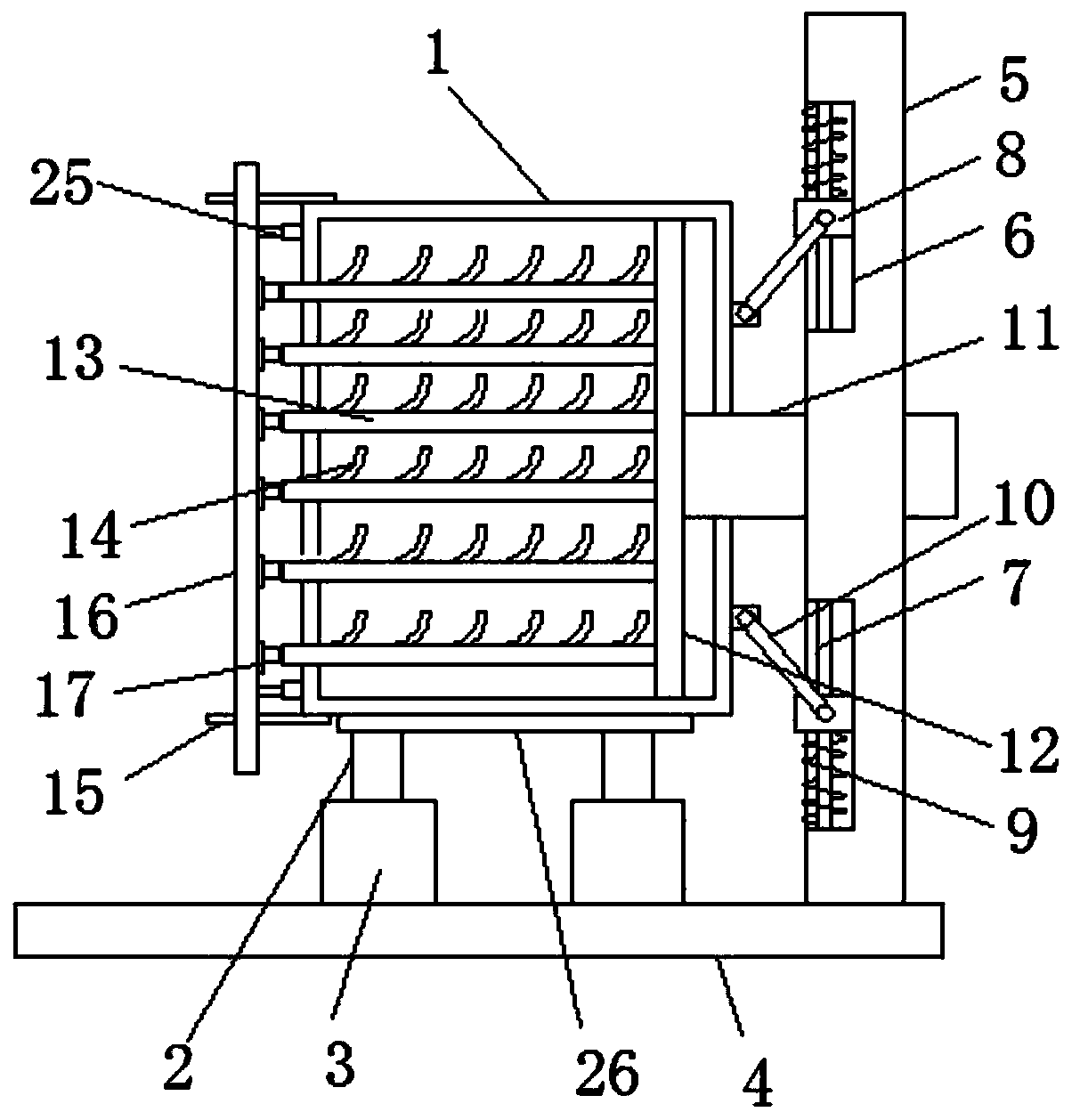
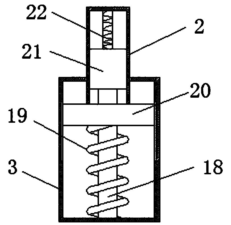
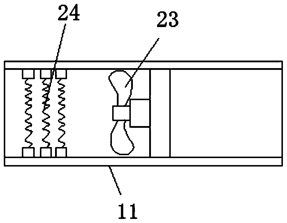
[0021] refer to Figure 1-3 , a new energy vehicle power storage device, comprising a casing 1, a support plate 26 is slidably installed on the bottom of the casing 1, a first column 2 is fixedly connected to the bottom of the support plate 26, and the bottom of the first column 2 is slidably connected to There is a second cylinder 3, the bottom of the second cylinder 3 is fixedly connected with a bottom plate 4, and the top of the bottom plate 4 is fixedly connected with a riser 5, and the side of the riser 5 close to the housing 1 is provided with two symmetrically arranged track grooves 6. A vertical bar 7 is fixedly installed in the track groove 6, a buffer block...


PUM


Abstract

The invention discloses a new energy automobile power storage device. The new energy automobile power storage device comprises a shell, wherein a support plate is arranged at the bottom of the shell in a sliding way, a first cylinder is fixedly connected to the bottom of the support plate, a second cylinder is connected to the bottom of the first cylinder in a sliding way, a bottom plate is fixedly connected to the bottom of the second cylinder, a vertical plate is fixedly connected to the top of the bottom plate, two rail grooves are formed in one side, near to the shell, of the vertical plate and are symmetrically arranged, vertical rods are fixedly arranged in the rail grooves, buffer blocks are connected to the vertical rods in a sliding way, springs sleeve the vertical rods, linkage rods are hinged with the buffer blocks, one end of each linkage rod is hinged with the shell, and an air inlet pipe is fixedly connected to one side, near to the vertical plate, of the shell and is connected with the vertical plate in a sliding way. By the new energy automobile power storage device, heat dissipation and temperature rising of the power storage device are achieved, the cooling effectis good, a favorable temperature environment is provided, meanwhile, a dustproof effect is achieved, a buffer effect is provided for a horizontal position and a vertical direction, the shock-resistance performance of the power storage device is greatly improved, and the service lifetime of the power storage device is prolonged.

Description

technical field [0001] The invention relates to the technical field of new energy vehicles, in particular to a power storage device for new energy vehicles. Background technique [0002] Existing automotive power storage devices will generate a lot of heat when they are working, and the heat will be dissipated through the heat dissipation holes. The working performance of the electric device is reduced, and the temperature of the electric storage device cannot be adjusted. At the same time, the shock resistance of the electric storage device is very poor. When the car is running, the vibration will cause great damage to the electric storage device. Therefore, a new energy vehicle is needed. storage device to solve the above problems. Contents of the invention [0003] The purpose of the present invention is to solve the shortcomings in the prior art, and propose a new energy vehicle power storage device. [0004] In order to achieve the above object, the present inventio...

Claims


Application Information

Patent Timeline
Patent Type & Authority Applications(China)
IPC IPC(8): H01M2/10H01M10/613H01M10/615H01M10/625H01M10/63H01M10/6563H01M10/6566H01M10/6571H01M50/249
CPCH01M10/613H01M10/615H01M10/625H01M10/63H01M10/6563H01M10/6566H01M10/6571H01M2220/20Y02E60/10
Inventor 胡勋勋
Owner 广东立胜综合能源服务有限公司
Why Eureka
Try Eureka