Split iron core stator double-layer winding structure and mounting method thereof

An iron core stator and double-layer winding technology, which is applied to the shape/style/structure of winding conductors, electromechanical devices, electric components, etc., can solve the problem of inability to ensure smooth entry of coils into slots, inability to achieve split stator splicing, and inability to proceed smoothly embedding and other issues

Pending Publication Date: 2018-10-16
SINOPAL (QINGDAO) ELECTRIC CO LTD
View PDF1 Cites 2 Cited by
  • Summary
  • Abstract
  • Description
  • Claims
  • Application Information

AI Technical Summary

Problems solved by technology

When splicing the stators of each lobe, under the existing technology, it is impossible to ensure that the effective side of the coil protruding out of the core can enter the groove smoothly without damaging the insulation, and the purpose of splicing the stator halves cannot be achieved.
If you embed the coil at the splicing position of the split stator after splicing, since the coil has an upper and lower side structure, and the split stator has been dipped in paint before splicing, the lower side of the splicing coil will not be able to be embedded smoothly
[0005] CN104995819B discloses a method for realizing the double-layer winding of the split stator. This structure designs the stator into a Z-shaped structure at the splicing position, but the above-mentioned structure has certain defects in terms of mechanical strength and electrical performance.

Method used


Image

  • Split iron core stator double-layer winding structure and mounting method thereof
  • Split iron core stator double-layer winding structure and mounting method thereof

Examples


Embodiment Construction

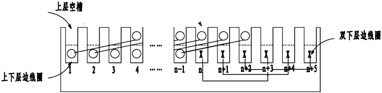
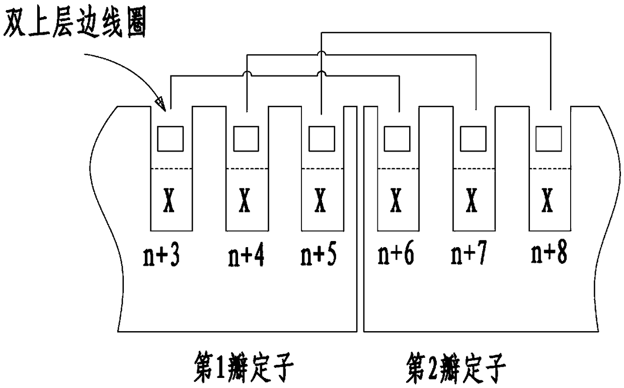
[0025] The invention discloses a double-layer winding structure of a split iron core stator, and the stator of the motor is in the axial direction. The stator is spliced ​​by multiple split stators. Viewed from the axial direction of the motor, the stator is spliced ​​by multiple (two or more) split stators in the circumferential direction. The splicing position can be located at the teeth of the iron core or at the groove of the iron core. Can be the same or different.

[0026] Each stator core includes a plurality of slots spaced apart along the circumference, and two coils are embedded in each slot. In said slot, the active sides of the two coils are stacked together. The upper half of the slot that defines the effective side of the coil without embedding is called the upper empty slot. At the splicing position of the one-lobe stator and the adjacent other-lobe stator, one-lobe stator has m-pitch upper empty slots, the other slots are embedded with coil effective sides, ...


PUM


Abstract

The invention discloses a split iron core stator double-layer winding structure and a mounting method thereof, wherein a stator is arranged along the axial direction of the motor; the stator is formedby splicing a plurality of split stators; each split stator iron core comprises a plurality of alveolus spaced along the circumference, and two coils are embedded in each alveoli; in the alveolus, the effective sides of the two coils are stacked together; the upper half of the alveoli without embedding the effective edges of the coils is defined as an upper empty alveoli; at the splicing positionof a split stator and another split stator adjacent thereto, the split stator is provided with an upper empty alveoli with m pitches, the other alveolus are embedded with effective edges of the coils, and the other split stator is provided with an upper empty alveoli with m pitches; when a plurality of split stators are spliced, m-pitch double-layer side coils are embedded in the upper layer empty alveoli. Compared with a motor in the prior art, the structure can realized a motor with a complete double-layer winding in a relatively simple manner without adversely affecting the reliability andoperational safety of the motor.

Description

technical field [0001] The invention relates to a low-speed large-scale motor, including modular assembly and manufacture of a generator and a motor, in particular to a split-core stator double-layer winding structure and an installation method thereof. Background technique [0002] A rotating electrical machine generally includes a stator and a rotor. For a high-power direct-drive low-speed motor, the size and weight of the motor increase with the increase of the power of the single machine, which makes it difficult to impregnate the stator or transport the motor. At present, an effective solution is to make the stator into a split structure, which has the advantages of being convenient for the dipping of the stator on the one hand, and convenient for transportation and on-site assembly on the other hand. [0003] For the stator split structure, the existing solution is mainly a split stator with a single-layer winding structure. Although this structure is easy to implement...

Claims


Application Information

Patent Timeline
Patent Type & Authority Applications(China)
IPC IPC(8): H02K3/12H02K3/28H02K15/085
CPCH02K3/12H02K3/28H02K15/085
Inventor 王小东肖怡钦王云郭强
Owner SINOPAL (QINGDAO) ELECTRIC CO LTD
Why Eureka
Try Eureka