Conductive bracket for motor

A technology of conductive brackets and conductive pins, applied in the direction of electrical components, electromechanical devices, electric components, etc., can solve problems such as easy loosening of connecting rods and conductive connecting pieces, deformation of PCBA boards, and unreasonable positioning and support, so as to avoid poor contact , improve efficiency, and reduce production costs

Pending Publication Date: 2018-10-16
JIANGSU LANGXIN ELECTRIC
View PDF0 Cites 0 Cited by
  • Summary
  • Abstract
  • Description
  • Claims
  • Application Information

AI Technical Summary

Problems solved by technology

However, this conductive bracket has the following disadvantages: 1. The metal rod is welded to the conductive connecting piece, the connecting piece is welded to the PCBA board, and the other end of the metal rod is welded to the winding. Shaped pins need to be aligned with the tiny connection holes of the PCBA board, which makes assembly difficult
2. The connection between the connecting piece of the current conductive bracket and the metal rod is only fixed by welding, and the length of the metal rod is rel

Method used


Image

  • Conductive bracket for motor
  • Conductive bracket for motor
  • Conductive bracket for motor

Examples


Embodiment Construction

[0029] The present invention will be further described in detail below through specific embodiments.

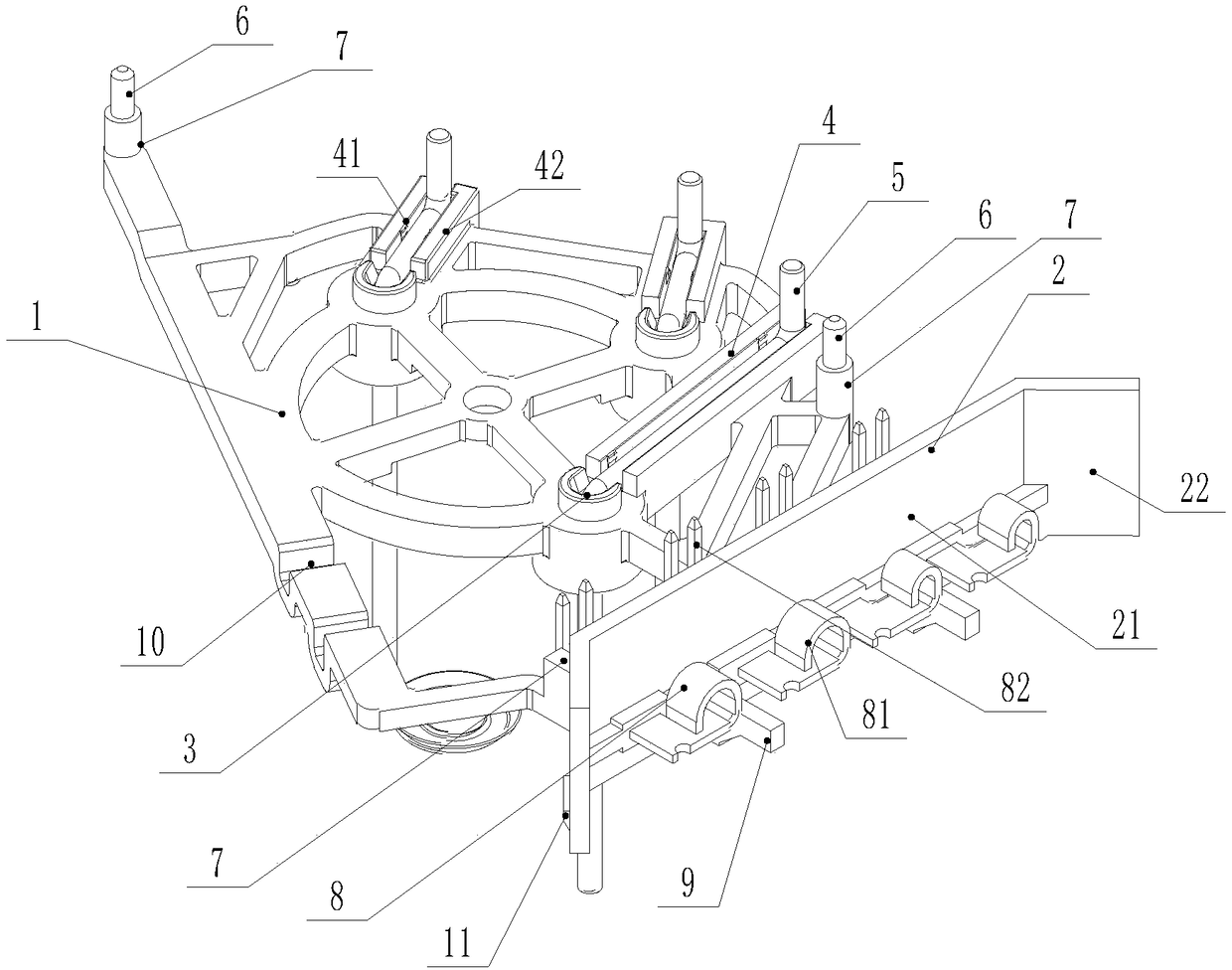
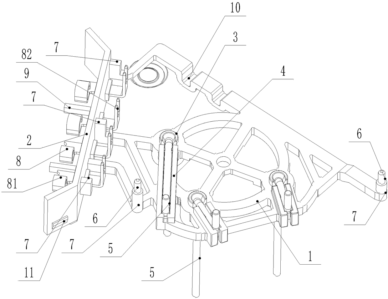
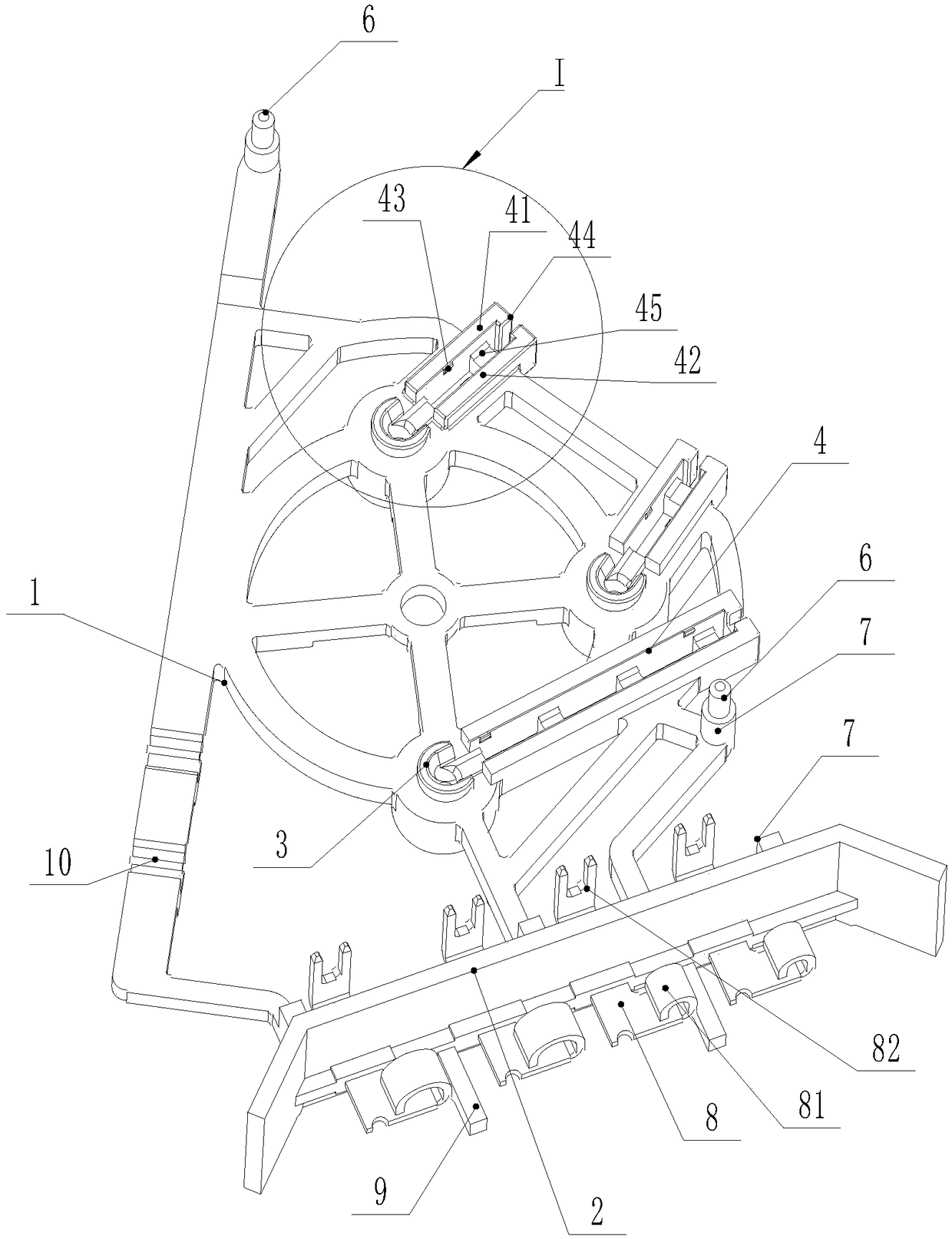
[0030] Such as Figure 1 to Figure 6 As shown, a conductive support for a motor is shown, and the conductive support is a hollow conductive support. It includes a plastic bracket body 1, three mounting holes 3 penetrating through the front and back are provided on the bracket body, and the back side of the bracket body 1 is provided with a positioning slot 4 that communicates with the three mounting holes 3 and extends along the back. In the example, the front side is the side close to the stator, and the reverse side is the side close to the PCBA board 12.

[0031] Each mounting hole 3 is filled with a conductive connecting rod 5. The tail section of the conductive connecting rod 5 is bent and embedded in the positioning slot 4, and the tail end of each conductive connecting rod 5 is bent from the positioning slot 4 The inwardly extending back side is used for electrical welding...


PUM


Abstract

The invention discloses a conductive bracket for a motor. The comprising a bracket body, wherein the bracket body is provided with three mounting holes, the back side of the bracket body is provided with a positioning insertion groove, each mounting hole is plugged with a conductive connecting rod, the tail end of each conductive connecting rod is bent and inlaid in the positioning insertiongroove, the tail end of each conductive connecting rod is bent and stretches out to the back side from the positioning insertion groove, the front end of each conductive connecting rod stretches out of thecorresponding mounting hole, one end of the bracket body is provided with a harness mounting plate, the harness mounting plate is provided with a harness conductive pin, and the bracket body is provided with a supporting structure for positioning on the back side. The conductive bracket has a reasonable structure, the mounting holes and the positioning insertion groove are formed in the conductivebracket to better mount the conductive connecting rods, the conductive connecting rods and a PCBA board are prevented from being displaced when assembled, the assembly precision is higher, a conductive connecting piece is not needed, the welding operation is reduced, and the conductive efficiency is improved.

Description

Technical field [0001] The invention relates to a conductive support used in a motor. Background technique [0002] The conductive support is a conductive connection part in the motor, and the function of the conductive support is to electrically connect the PCBA board in the motor and the winding of the motor. The conductive support is placed in the heat dissipation cover of the motor, and the PCBA board is set on the conductive support and transfers heat with the heat dissipation cover through thermally conductive glue. The current conductive support main structure includes a conductive connection sheet and a plastic coated outside the conductive connection sheet A bracket member, the conductive connecting piece has a pointed pin bent to the opposite side, the pointed pin is inserted into the connection hole of the PCBA board and then welded and fixed, and the plastic bracket member exposes the conductive connecting piece, and then three metal The rod is welded on the exposed ...

Claims


Application Information

Patent Timeline
IPC IPC(8): H02K11/00
CPCH02K11/0094
Inventor 戚纯波徐迎宾陈志强
Owner JIANGSU LANGXIN ELECTRIC
Why Eureka
Try Eureka