
Dust-proof polishing machine

A polishing machine, dust-proof technology, applied in the field of mechanical processing, can solve the problems of environmental hazards, dust can not be completely closed dust, no automatic collection of iron filings, etc., to achieve the effect of improving the suction rate

Inactive Publication Date: 2018-10-19
NANTONG ZHONGLV GEAR CO LTD
View PDF0 Cites 0 Cited by
  • Summary
  • Abstract
  • Description
  • Claims
  • Application Information

AI Technical Summary

Problems solved by technology

[0002] The polishing machine is mostly used to process the surface of the parts. When the polishing machine uses a grinding wheel with a larger particle size to process the surface of the part, iron filings will be generated. When the polishing machine uses a grinding wheel with a smaller particle size to process the surface of the part, metal dust will be generated. Now The polishing machine in the prior art is provided with dust removal structure, and this dust removal structure is only used for sucking metal dust in a relatively closed chamber, and does not process the dust sucked into the chamber, however, due to the strong diffusion of dust The nature of the chamber can not completely seal the dust, and the dust can still spread out of the chamber and cause harm to the environment. In addition, the polishing machine in the prior art does not have the function of automatically collecting iron filings, so that the iron filings can only be collected manually

Method used


Image

  • Dust-proof polishing machine

Examples


Embodiment Construction

[0010] In order to deepen the understanding of the present invention, the present invention will be further described below in conjunction with the embodiments and accompanying drawings. The embodiments are only used to explain the present invention and do not constitute a limitation to the protection scope of the present invention.

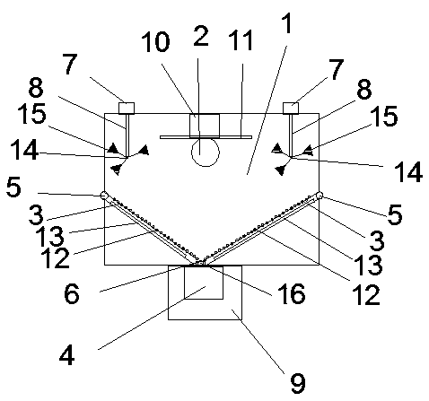
[0011] Such as figure 1 It is a specific embodiment of the present invention, and its structure includes: a cover body 1, a grinding wheel 2, a dust suction pipe 3 and an air suction pump 4, symmetrical clamps 5 are arranged on both sides of the cover body 1, and the bottom of the cover body 1 A snap ring 6 is provided, and the suction pipe 3 is fixed inside the cover body 1 through the clip 5 and the snap ring 6. A symmetrical motor 7 is provided on the top of the cover body 1, and a rotating shaft 8 is provided at one end of the motor 7, and the rotating shaft 8 is located on the Inside the cover body 1, the bottom of the cover body 1 is provid...


PUM


Abstract

The invention discloses a dust-proof polishing machine. The dust-proof polishing machine structurally comprises a housing body, a grinding wheel and an air suction pump. Symmetrical clamping hoops arearranged at the two sides of the housing body. A clamping ring is arranged at the bottom of the housing body. Dust suction pipes are fixed into the housing body through the clamping hoops and the clamping ring. Symmetrical motors are arranged at the top of the housing body. A rotating shaft is arranged at one end of each motor. The rotating shafts are located inside the housing body. A collectionbox is arranged at the bottom of the housing body. The air suction pump is fixed in the collection box. The top of the housing body is provided with a driving device used for driving the grinding wheel. The driving device is located between the motors. The grinding wheel is fixed to the driving device. The grinding wheel and the driving device are located inside the housing body. The top of the grinding wheel is provided with a baffle. The baffle is located between the two rotating shafts. The dust-proof polishing machine is reasonable in structure; and dust inside the polishing machine can be cleared away, and meanwhile, certain metal chippings can be cleared and collected.

Description

Technical field: [0001] The invention relates to the technical field of mechanical processing, in particular to a dust-proof polishing machine. Background technique: [0002] The polishing machine is mostly used to process the surface of the parts. When the polishing machine uses a grinding wheel with a larger particle size to process the surface of the part, iron filings will be generated. When the polishing machine uses a grinding wheel with a smaller particle size to process the surface of the part, metal dust will be generated. Now The polishing machine in the prior art is provided with dust removal structure, and this dust removal structure is only used for sucking metal dust in a relatively closed chamber, and does not process the dust sucked into the chamber, however, due to the strong diffusion of dust The nature of the chamber can not completely seal the dust, and the dust can still spread out of the chamber and cause harm to the environment. In addition, the polish...

Claims


Application Information

Patent Timeline
Patent Type & Authority Applications(China)
IPC IPC(8): B24B29/00B24B55/06B24B55/12
CPCB24B29/00B24B55/06B24B55/12
Inventor 潘志进
Owner NANTONG ZHONGLV GEAR CO LTD
Learn More