A built-in range hood oil tank installation structure assembly

A technology of installation structure and engine oil tank, which is applied in the direction of oil fume removal, heating method, household stove/stove, etc. It can solve the problems of low air suction rate and oil fume absorption rate, hindering the smooth entry of oil fume into the filter screen, etc., so as to improve the air suction Efficiency and oil fume absorption rate, enhanced smoothness, and the effect of eliminating the convex structure

Active Publication Date: 2016-08-10
HAIER GRP CORP +1
View PDF5 Cites 0 Cited by
  • Summary
  • Abstract
  • Description
  • Claims
  • Application Information

AI Technical Summary

Problems solved by technology

[0006] In order to overcome the defect that the bottom surface of the oil tank in the existing oil tank installation structure assembly is obviously higher than the outer surface of the smoke collecting chamber, forming a convex structure, which prevents the oil smoke from entering the filter screen smoothly, the technical problem to be solved by the present invention is to propose a built-in The installation structural components of the oil tank of the range hood can effectively solve the problem of low air suction rate and oil fume absorption rate of the traditional range hood, and significantly enhance the smoothness of the oil fume entering the filter screen, and the structure is beautiful, without protrusions, and the operation noise is small

Method used


Image

  • A built-in range hood oil tank installation structure assembly
  • A built-in range hood oil tank installation structure assembly
  • A built-in range hood oil tank installation structure assembly

Examples


Embodiment 1

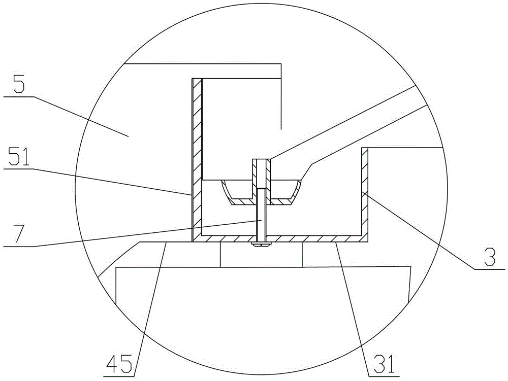
[0030] Example 1, the hood includes a left hood, a right hood, a front hood 4 and a rear hood 5, the oil groove 3 near the side where the front hood 4 is located is a rectangular groove, and the oil groove 3 The bottom surface 31 is at the same level as the outer surface 45 of the fume hood.

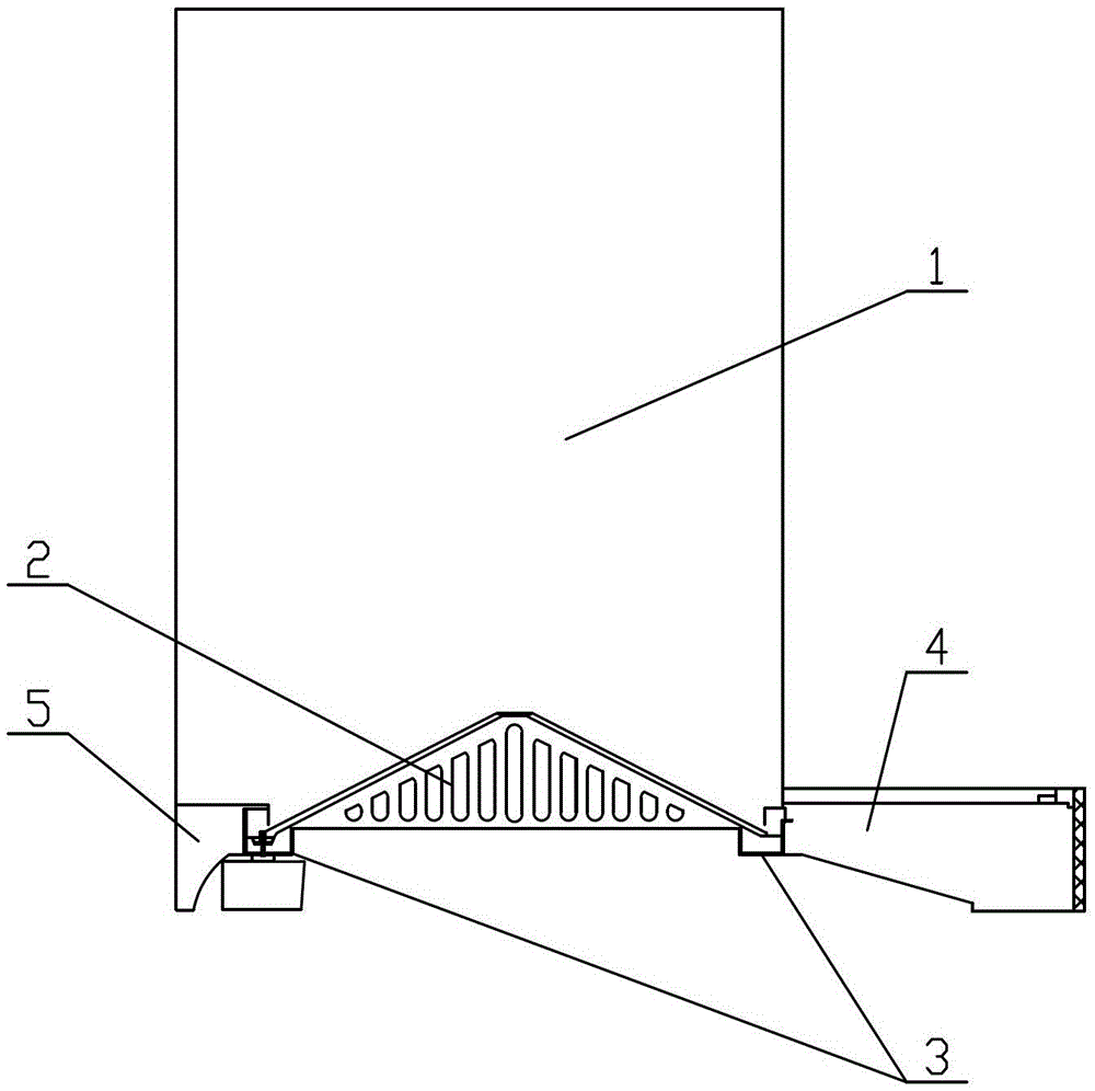
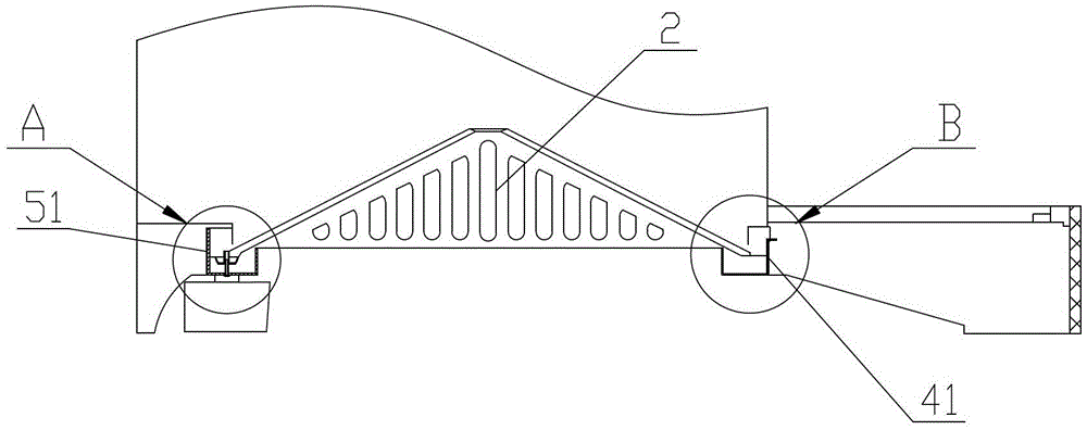
[0031] Such as figure 1 , 2 , 3 and 4 are schematic diagrams of the range hood, the built-in range hood oil tank installation structure assembly, part A and part B respectively.

[0032] Such as figure 1 As shown, a built-in range hood oil tank installation structure assembly includes a housing 1, a filter screen 2 and a fume cover, the filter screen 2 is arranged at the lower part of the housing 1, and the fume cover is arranged at the filter screen 2, an oil tank 3 is arranged below the bottom edge of the filter screen 2, the left smoke hood is arranged under the left side of the housing, and the right smoke hood is arranged on the right side of the housing Below, the front smoke c...

Embodiment 2

[0043] In Embodiment 2, the oil tank 3 near the side where the front hood 4 is located is a trapezoidal groove, and the bottom surface 31 of the oil tank 3 is at the same level as the outer surface 45 of the hood.

[0044] Such as Figure 5 As shown, the oil tank 3 is placed inside a part of the smoke collection chamber, and a part of the smoke collection chamber is composed of the right side wall on the left fume hood, the left side wall on the right fume hood, The rear side wall 41 on the front hood 4 , the front side wall 51 on the rear hood 5 and the lower surface of the filter screen 2 constitute.

[0045] The difference from Example 1 is that the oil tank 3 near the side where the front hood 4 is located is a trapezoidal tank, and the hypotenuse is on the right side of the oil tank 3, thereby effectively avoiding that when the oil tank 3 is a rectangular tank, the right angle of the rectangular tank is right-angled. The defect that has a certain influence on the oil fum...

Embodiment 3

[0046] Embodiment 3, the oil groove 3 near the side where the front hood 4 is located is a triangular groove.

[0047] Such as Image 6 As shown, the oil tank 3 is placed inside a part of the smoke collection chamber, and a part of the smoke collection chamber is composed of the right side wall on the left fume hood, the left side wall on the right fume hood, The rear side wall 41 on the front hood 4 , the front side wall 51 on the rear hood 5 and the lower surface of the filter screen 2 constitute.

[0048] Different from Embodiment 1, the oil groove 3 near the side where the front hood 4 is located is a triangular groove, and this oil groove 3 itself hardly has any influence on the oil fume flow rate entering the filter screen 2, but The capacity of the tank itself is relatively small, which is suitable for larger range hoods. Since the range hood has a larger volume at this time, the capacity of the oil tank 3 is also larger.


PUM


Abstract

The invention discloses an embedded oil groove mounting structure assembly of a range hood, and belongs to the field of range hood parts. The embedded oil groove mounting structure assembly comprises a housing, a filter screen arranged at the lower part of the housing and a smoke hood arranged on the periphery of the filter screen; an oil groove is formed below the edge of the bottom of the filter screen; the smoke hood comprises a left smoke hood, a right smoke hood, a front smoke hood and a rear smoke hood; the right side all of the left smoke hood, the left side wall of the right smoke hood, the rear side wall of the front smoke hood, the front side wall of the rear smoke hood and the lower surface of the filter screen form a part of a smoke collection cavity; the whole oil groove is embedded inside a part of the smoke collection cavity; and the bottom surface of the oil groove and the outer surface of the smoke hood are located on the same horizontal surface. The embedded oil groove mounting structure assembly can effectively solve the problem that the traditional range hood is not high in air suction rate and smoke suction rate, and the smoothness of oil smoke entering the filter screen can be obviously strengthened; and the assembly is attractive in structure, free of bulges and low in running noise.

Description

technical field [0001] The invention relates to the field of range hood accessories, in particular to a built-in range hood oil tank installation structure assembly. Background technique [0002] The existing range hood oil tank and filter screen are divided into the following two types according to their structure and installation method: [0003] One is to use a conical filter screen, which is in the shape of a pyramid. This structure requires an oil cup at the bottom of the filter screen to collect the waste oil flowing out along the oil guide groove. Due to the effect of gravity, the oil cup must be in the cone The lowest end of the filter screen, that is, the position of the conical top of the filter screen, is convenient for collecting waste oil, but this installation method will inevitably reduce the air intake area of ​​the oil fume and affect the smoothness of oil fume collection. [0004] The other is to use an inverted conical filter screen, which is in the shape...

Claims


Application Information

Patent Timeline
Patent Type & Authority Patents(China)
IPC IPC(8): F24C15/20
Inventor 薄韶辉付刚杜艳玲赵良
Owner HAIER GRP CORP
Why Eureka
Try Eureka