
Bicycle transmission device

A transmission device and bicycle technology, applied to chain/belt transmission devices, vehicle parts, vehicle gearboxes, etc., can solve the problems of increasing manufacturing difficulty, manufacturing cost, and complex structure, so as to reduce manufacturing cost and manufacturing difficulty, and simplify the structure Effect

Pending Publication Date: 2018-10-19
ZHANGJIAGANG CHUANJUN VEHICLE IND CO LTD
View PDF0 Cites 0 Cited by
  • Summary
  • Abstract
  • Description
  • Claims
  • Application Information

AI Technical Summary

Problems solved by technology

[0003] With the development of the tourism industry, the application of two-person straight-line pedal bicycles is more and more extensive. The two-person straight-line pedal bicycles in the prior art generally need to be provided with four straight-line pedal mechanisms, that is, the left and right feet of each rider are equal to each other. Separately set a linear stepping mechanism that matches it, the disadvantages of this structure are: 1. The structure is relatively complicated, which increases the difficulty and cost of manufacturing

Method used


Image

  • Bicycle transmission device

Examples


Embodiment 1

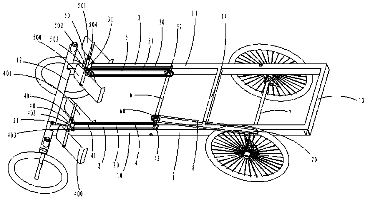
[0021] ginseng figure 1 As shown, a bicycle transmission device includes: a vehicle frame 1 and a first guide mechanism 2 arranged on the vehicle frame 1, a second guide mechanism 3, a first linear pedal mechanism 4, a second linear pedal mechanism 5, a middle Transmission shaft 6 and rear wheel transmission shaft 7.

[0022] The vehicle frame 1 includes a first longitudinal beam 10, a second longitudinal beam 11, a first beam 12 arranged at one end of the first longitudinal beam 10 and the second longitudinal beam 11, a first crossbeam 12 arranged at one end of the first longitudinal beam 10 and the second longitudinal beam 11, the second beam 13 at the other end and the intermediate beam 14 arranged between the first longitudinal beam 10 and the second longitudinal beam 11, the first guide mechanism 2 is arranged on the first longitudinal beam 10, and the second guide The mechanism 3 is arranged on the second longitudinal beam 11 .

[0023] The first guide mechanism 2 incl...

Embodiment 2

[0031] In Embodiment 1, the first transmission belt 41 and the second transmission belt 51 drive the rear wheel transmission shaft 7 through the transmission of the intermediate transmission shaft 6, but in this embodiment, no intermediate transmission shaft is provided, and they are directly on the rear wheel transmission shaft 7. A first transmission wheel matched with the first transmission belt 41 and a second transmission wheel matched with the second transmission belt 51 are provided, and the rear wheel transmission shaft 7 is directly driven by the first transmission belt 41 and the second transmission belt 51 .

[0032] To sum up, the bicycle transmission device in the present invention reduces the four sets of linear pedaling mechanisms in the prior art to two sets of linear pedaling mechanisms, and correspondingly improves the structure of the pedaling parts that match the two sets of linear pedaling mechanisms. Therefore, the structure is greatly simplified, and the ...


PUM


Abstract

The invention relates to a bicycle transmission device which comprises a bicycle frame, a first guide mechanism, a second guide mechanism, a first linear stepping mechanism, a second linear stepping mechanism and a rear wheel transmission shaft. The first guide mechanism comprises a first guide rail and a first sliding seat. The second guide mechanism comprises a second guide rail and a second sliding seat. The first linear stepping mechanism comprises a first stepping piece and a first transmission belt. The first stepping piece comprises a first pedal, a second pedal and a first connecting piece. The two free tail ends of the first transmission belt are connected with the first stepping piece or the first sliding seat. The second linear stepping mechanism comprises a second stepping piece and a second transmission belt. The second stepping piece comprises a third pedal, a fourth pedal and a second connecting piece. The two free tail ends of the second transmission belt are connectedwith the second stepping piece or the second sliding seat. The structure is greatly simplified.

Description

【Technical field】 [0001] The invention relates to the field of bicycles, in particular to a bicycle transmission device. 【Background technique】 [0002] Most of the bicycle driving mechanisms in the prior art adopt the way of pedaling in a circle, which has a dead point of force, that is, when the direction of the pedaling force is in line with the crank, no matter how much force is used, the bicycle cannot be moved forward. Do circular motions, pedaling frequency is not high. Therefore, there was a straight-line stepping bicycle in the industry afterwards. [0003] With the development of the tourism industry, the application of two-person straight-line pedal bicycles is more and more extensive. The two-person straight-line pedal bicycles in the prior art generally need to be provided with four straight-line pedal mechanisms, that is, the left and right feet of each rider are equal to each other. A linear stepping mechanism matched with it is separately provided, and the ...

Claims


Application Information

Patent Timeline
IPC IPC(8): B62M1/24B62M1/28B62M9/10
CPCB62M1/24B62M1/28B62M9/105
Inventor 黄英可
Owner ZHANGJIAGANG CHUANJUN VEHICLE IND CO LTD
Learn More