Damper for automotive suspension system

A technology of automobile suspension and shock absorber, applied in shock absorbers, springs/shock absorbers, shock absorbers, etc., can solve problems such as gaps, dust cover damage, waste of resources, etc., and achieve stable connection and installation , Reduce the cost of use, increase the effect of the nut falling off

Pending Publication Date: 2018-10-19
钱盛
View PDF0 Cites 1 Cited by
  • Summary
  • Abstract
  • Description
  • Claims
  • Application Information

AI Technical Summary

Problems solved by technology

[0005] Aiming at the deficiencies of the prior art, the present invention provides a shock absorber for an automobile suspension system, which is equipped with lifting lugs and dust covers that are easy to replace separately, low in use cost, stable connection of structural parts, monitoring of the gap between the piston and the inner wall of the working cylinder and Fault warning and other advantages solve the problem that in daily use, the connection between the lifting lug and the bolt is easy to loose due to bearing friction. When replacing the lifting lug, the entire piston rod and the dust cover are often replaced together, which not only costs a lot , also caused a waste of resources, and the dust cover is easily damaged due to impact due to its thin wall, and the replacement is also replaced together with the lifting lug. On the other hand, the piston in the shock absorber and the inner wall of the working cylinder are easily There will be gaps, thus losing the shock absorption effect. It is difficult for the user to judge the fault of the shock absorber unless the user has sufficient experience, and the problem of continuing to drive the car is prone to dangerous situations.

Method used


Image

  • Damper for automotive suspension system
  • Damper for automotive suspension system
  • Damper for automotive suspension system

Examples


Embodiment Construction

[0030] The following will clearly and completely describe the technical solutions in the embodiments of the present invention with reference to the accompanying drawings in the embodiments of the present invention. Obviously, the described embodiments are only some, not all, embodiments of the present invention. Based on the embodiments of the present invention, all other embodiments obtained by persons of ordinary skill in the art without making creative efforts belong to the protection scope of the present invention.

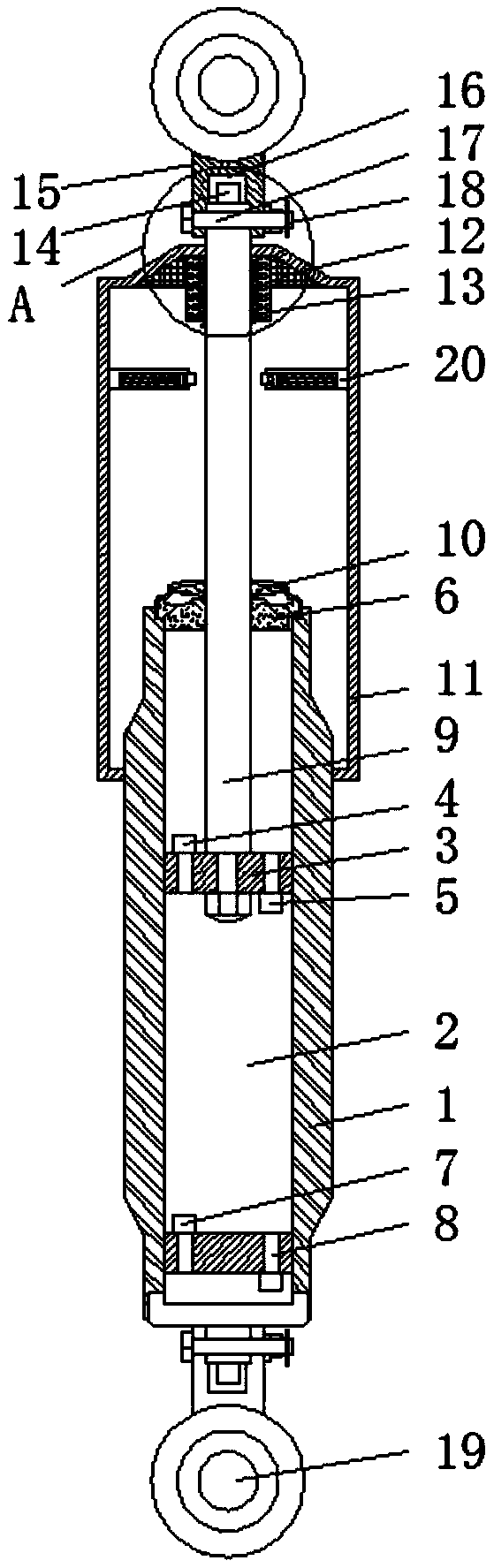
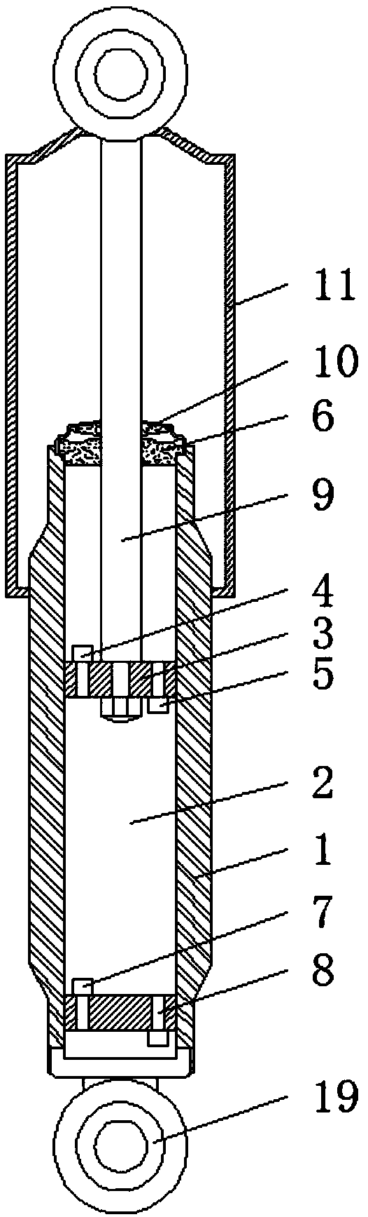
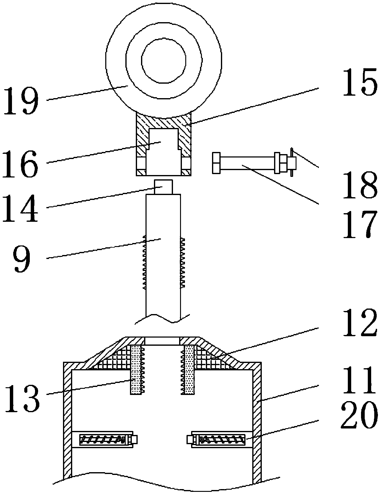
[0031] see Figure 1-7, a shock absorber for an automobile suspension system, comprising an oil storage cylinder 1, the inside of the oil storage cylinder 1 is fixedly sleeved with a working cylinder 2, the inside of the working cylinder 2 is slidably connected with a sealing piston 3, and the inside of the sealing piston 3 An extension valve 4 and a flow valve 5 are fixedly installed at the left and right ends of the cylinder, guide seats 6 are fixedly instal...


PUM

PropertyMeasurementUnit
Thicknessaaaaaaaaaa

Abstract

The invention relates to the technical field of automobile parts, and discloses a damper for an automotive suspension system. The damper comprises an oil storage cylinder barrel. An operation cylinderbarrel is fixedly sleeved with the oil storage cylinder barrel. A sealing piston is slidably connected into the operation cylinder barrel. A rebound valve and a flow valve are fixedly mounted at theleft end and the right end of the interior of the sealing piston correspondingly. Guide holders are fixedly mounted at the upper end and the lower end of the operation cylinder barrel. A compression valve and a compensation valve are fixedly mounted at the left end and the right end of the interior of the lower guide holder correspondingly. According to the damper for the automotive suspension system, by arranging a protrusion block, a connecting barrel and a clamping groove, a hoisting lug and a piston rod are connected in a detachable clamping-connection mode instead of a traditional weldingmode, meanwhile, a dust cover and the piston rod are in threaded connection, the top connecting rod limits the dust cover in the upward direction, thus, the dust cover can be independently replaced and dismounted, quick-wear parts such as the hoisting lug and the dust cover are independently dismounted and replaced, the application cost is reduced, and resources are saved.

Description

technical field [0001] The invention relates to the technical field of auto parts, in particular to a shock absorber for an auto suspension system. Background technique [0002] Suspension shock absorber is the vibration of the elastic element in the suspension system due to the impact. In order to improve the ride comfort of the car, the shock absorber is installed in parallel with the elastic element in the suspension. Although the shock-absorbing spring can filter the vibration of the road surface, the spring itself is still There will be reciprocating motion, and the shock absorber is there to dampen this spring jump. Its working principle is that when the frame (or body) and the axle vibrate and there is relative movement, the piston in the shock absorber moves up and down, and the oil in the shock absorber cavity repeatedly flows from one cavity through different valves. In the other cavity, the friction between the hole wall and the oil and the internal friction betw...

Claims


Application Information

Patent Timeline
IPC IPC(8): F16F9/19F16F9/32F16F9/38F16F9/54
CPCF16F9/19F16F9/3264F16F9/3271F16F9/38F16F9/54
Inventor 钱盛徐东洁沈旭
Owner 钱盛
Why Eureka
Try Eureka