Method for determining damage of water pipe with monitoring system

A technology for monitoring systems and determining methods, applied in pipeline systems, mechanical equipment, gas/liquid distribution and storage, etc., can solve problems such as difficult to bear losses, difficult to determine damage points, difficult maintenance, etc., to reduce water loss losses Risks, timely detection of pipeline damage, and the effect of reducing work and costs

Inactive Publication Date: 2018-10-19
东莞产权投资有限公司
View PDF0 Cites 3 Cited by
  • Summary
  • Abstract
  • Description
  • Claims
  • Application Information

AI Technical Summary

Problems solved by technology

[0002] Some large-scale communities are very large, with large communities, many buildings, more paths, and complex distribution of buildings. It is difficult to plan the paths of water pipes in large communities, and there are often problems of simplification and extensiveness. The laying of water pipe networks is extremely unreasonable, and many unnecessary Repeated laying of pipes leads to waste of pipes and space resources, and because the total length of pipes is often extended a lot, and the longer the pipe, the greater the chance of damage
[0003] In addition, because the water pipes are laid underground, the laying is difficult, and the maintenance is extremely difficult: it is difficult to determine the damage point, and it is generally necessary to dig a large section of road in several places during maintenance to finally determine the damage point of the pipeline. Difficult; in addition, this is the external pipeline of the building, which has a great impact and involves a wide range of areas. Once the pipeline is damaged, one building or several buildings will be cut off for a period of time, which will have a great impact on the residents and it is difficult to bear the loss; so the accurate Determining the damage point of the pipeline is of great significance to the majority of ordinary households and the water company that maintains the water pipes

Method used


Image

  • Method for determining damage of water pipe with monitoring system
  • Method for determining damage of water pipe with monitoring system

Examples


Embodiment Construction

[0022] The present invention is described in detail below in conjunction with accompanying drawing:

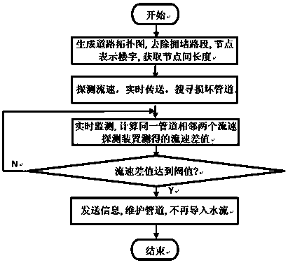
[0023] In this example, the large-scale community water pipe flow velocity detection device is installed on the inside or outside of the water pipe in the water pipe, and is arranged at an even distance. At least two water pipe flow velocity detection devices are placed in the same pipeline and the same flow direction. A large-scale community water pipe contains several such devices. Each device has a unique address.

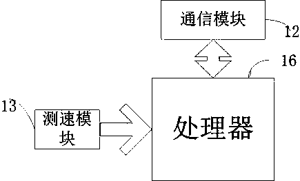
[0024] figure 1 A diagram of a flow velocity detection device according to an embodiment of the present invention is shown. A speed detection device includes a communication module 12, a speed measurement module 13, and a processor 16. The speed measurement module 13 obtains the specific flow velocity of a certain pipeline of a water pipe in a large community at a certain moment, and obtains the flow velocity and direction of the water flow, etc.

[0025] Whe...


PUM


Abstract

The invention discloses a method for determining the damage of a water pipe with a monitoring system. The monitoring system comprises multiple flow rate detection devices installed in the water pipe.Each flow rate detection device comprises a speed detection module for detecting the flow rate and a processor. The processors receive data collected by the speed detection modules and upload the datato a central computer through communication modules after processing, and meanwhile the communication modules send a received command from the central computer to a maintenance engineering command center and workers after processing. Pipeline damage is detected in time, the damaged pipe is maintained quickly, and the maintenance path is optimized. By the adoption of the method, the work and costof maintenance and repair can be greatly reduced, the difficulty of maintenance is reduced, and the installation and maintenance by workers are easier; and the satisfaction of building users is improved, and the risk of residents suffering from water stop loss is greatly reduced.

Description

technical field [0001] The invention relates to a water pipe damage determination method with a monitoring system. Background technique [0002] Some large-scale communities are very large, with large communities, many buildings, more paths, and complex distribution of buildings. It is difficult to plan the paths of water pipes in large communities, and there are often problems of simplification and extensiveness. The laying of water pipe networks is extremely unreasonable, and many unnecessary Repeated laying of pipes causes waste of pipe materials and space resources, and because the total length of pipes is often extended a lot, the longer the pipe, the greater the chance of damage. [0003] In addition, because the water pipes are laid underground, the laying is difficult, and the maintenance is extremely difficult: it is difficult to determine the damage point, and it is generally necessary to dig a large section of road in several places during maintenance to finally d...

Claims


Application Information

Patent Timeline
Patent Type & Authority Applications(China)
IPC IPC(8): F17D5/02
CPCF17D5/02
Inventor 不公告发明人
Owner 东莞产权投资有限公司
Why Eureka
Try Eureka