Visual crack device for simulating crack closure and leak-off and working method thereof

A technology for simulating cracks and fractures, applied in the field of simulated and visualized fracture devices, can solve the problems of inaccurate experimental results and inability to simulate repeated fracturing, and achieve the effect of improving accuracy

Inactive Publication Date: 2018-10-19
CHINA UNIV OF PETROLEUM (BEIJING)
View PDF18 Cites 13 Cited by
  • Summary
  • Abstract
  • Description
  • Claims
  • Application Information

AI Technical Summary

Problems solved by technology

[0004] Aiming at the fact that the prior art cannot simulate repeated fracturing and the experimental results are not accurate enough, the present invention provides a visual fracture device and its working method for simulating fracture closure and fluid loss

Method used


Image

  • Visual crack device for simulating crack closure and leak-off and working method thereof
  • Visual crack device for simulating crack closure and leak-off and working method thereof
  • Visual crack device for simulating crack closure and leak-off and working method thereof

Examples


Embodiment 1

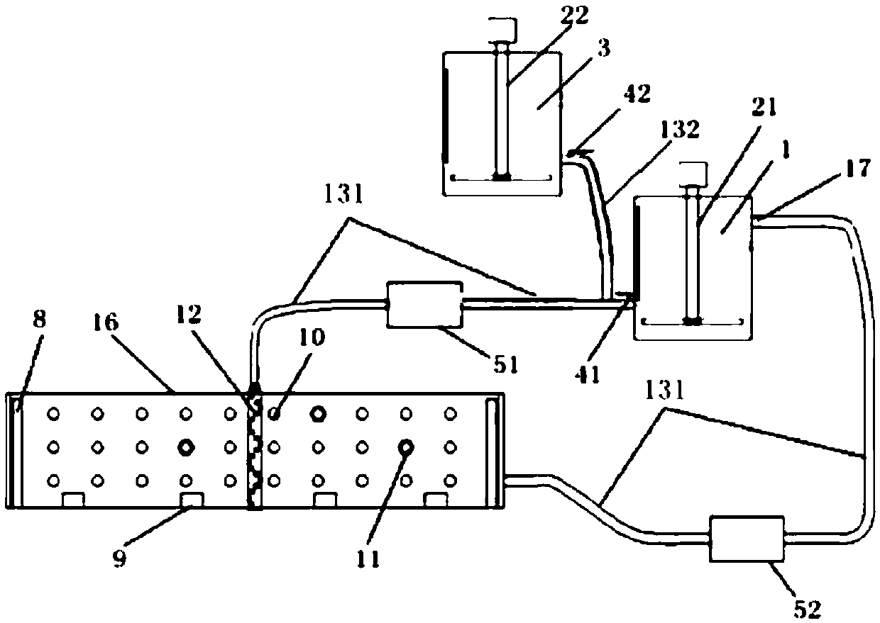
[0057] Such as figure 1 As shown, a visualized fracture device for simulating fracture closure and fluid loss in this embodiment includes a fracturing fluid tank 1 , a sand mixing fluid tank 3 , a fracturing fluid pump 51 , a visualized fracture simulation plate 16 and a drainage pump 52 . Wherein, the discharge port of the fracturing fluid tank 1, the fracturing fluid pump 51, the visualized fracture simulation plate 16, the drainage pump 52, and the circulating feed port 17 of the fracturing fluid tank are connected through the main fracturing pipeline 131 to form a circulation loop, The outlet of the sand mixing fluid tank 3 is connected to the main fracturing pipeline 131 located between the fracturing fluid pump 51 and the outlet of the fracturing fluid tank 1 through a branch line 132 . The fracturing fluid tank 1 and the sand mixing fluid tank 3 are respectively connected to the fracturing fluid pump 1 through a three-way joint. The circulation loop of the whole device...

Embodiment 2

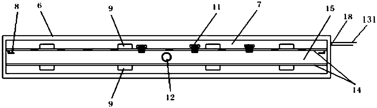
[0065] The difference between the structure of this embodiment and Embodiment 1 lies in the wall surface. The wall surface of this embodiment includes an artificial wall surface simulating a real rock formation, which is used to simulate the influence of the real lithologic reservoir wall surface on the movement law of proppant. Wall surface clamping grooves 8 are provided at both ends of the flat plate 14 with the filtration holes 10 for installing artificially made crack walls.

Embodiment 3

[0067] Using the working method of a visualized fracture device for simulating fracture closure and fluid loss in Example 2, according to the slug type fracturing process, the steps are as follows:

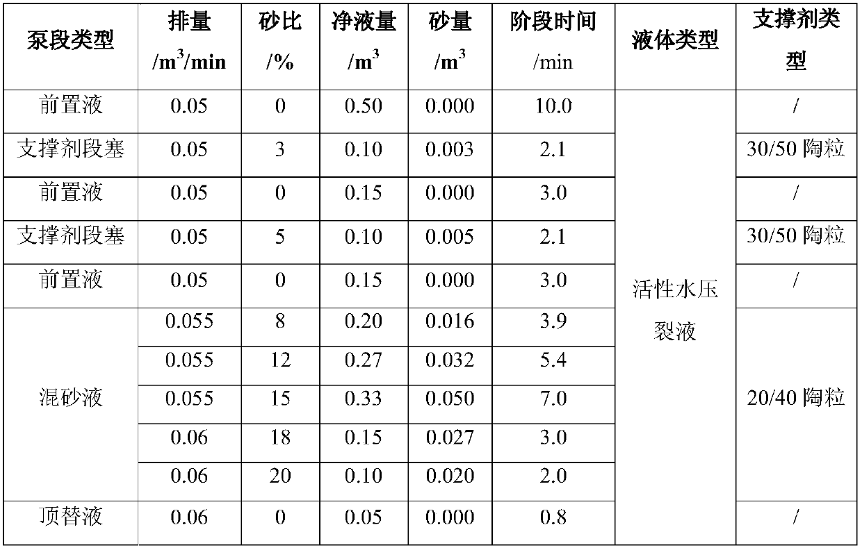
[0068] (1) According to the principle of similarity, according to the three-dimensional size of the fracture in the field construction, the viscosity of the fracturing fluid required for the experiment is calculated to be 20mPa·s, and the proppant dose is 0.15m 3 , fracturing fluid volume 2.1m 3 , Experimental displacement 0.05 ~ 0.06m 3 / min, the number of perforation holes is 16 / m, and the slug time is 4.2min, and the slug fracturing pump injection program is designed, as shown in Table 1;

[0069] (2) Prepare active water fracturing fluid and 30 / 50 and 20 / 40 ceramic proppant according to the required proppant amount and fracturing fluid volume calculated in step (1), and configure fracturing fluid and sand mixing fluid, which will be used as The fracturing fluid of the pad fl...


PUM


Abstract

A visual crack device for simulating crack closure and leak-off and a working method thereof are disclosed. The visual crack device includes: a visual crack simulation plate, a fracturing fluid pump,and a fracturing fluid tank which are connected to from a circulation loop through a fracturing main pipeline; and a sand mixing liquid tank which is connected to the fracturing main pipeline betweena discharging opening of the fracturing fluid tank and the fracturing fluid pump through a branch pipeline; the exterior of the crack simulation plate is a rectangular container, and the interior of the crack simulation plate is divided into three layers by two flat plates; a simulation fracturing crack is arranged between the flat plates; a reservoir simulation space is formed between one flat plate and the rectangular container; stress simulation driving devices are arranged on outer surfaces of the flat plates; leak-off holes are formed in the flat plates; a fluid outlet of the rectangularcontainer is positioned on the bottom of the reservoir simulation space, and is connected to a circulating inlet of the fracturing fluid tank; one end of a shaft is connected to the fracturing main pipeline, and the other end of the shaft is positioned in the fracturing crack; and perforation holes are distributed in the surface of the shaft. The visual crack device completes the leak-off function, can achieve crack closure and re-opening, and can improve the accuracy of the experimental results.

Description

technical field [0001] The invention relates to a simulated and visualized fracture device, which belongs to the technical field of oil and gas field development. Background technique [0002] Hydraulic fracturing is a very complex stimulation process for oil and gas wells. The principle of hydraulic fracturing stimulation is to use the surface high-pressure pump group to pump fracturing fluid into the well with a displacement exceeding the absorption capacity of the formation, and to suffocate high pressure at the bottom of the well. When the pumping pressure overcomes the ground stress near the borehole wall and reaches the tensile strength of the rock, fractures will be generated at the bottom of the well; then the mixture of fracturing fluid and proppant is pumped in, and the support of the proppant is used to prevent the fractures from completely closing. A certain length of sand-filled fractures with flow-conducting capacity are formed in the middle to provide reservo...

Claims


Application Information

Patent Timeline
Patent Type & Authority Applications(China)
IPC IPC(8): G01M10/00
CPCG01M10/00
Inventor 刘欣佳靳建虎张遂安赵威杜军军
Owner CHINA UNIV OF PETROLEUM (BEIJING)
Why Eureka
Try Eureka