Check patentability & draft patents in minutes with Patsnap Eureka AI!

Assembled spring operating mechanism

An operating mechanism and assembled technology, which is applied to the contact operating mechanism, power device inside the switch, electrical components, etc., can solve the requirements of high component strength, poor matching of output force characteristics and reaction force characteristics, and processing accuracy requirements of parts Advanced problems, to achieve the effect of reducing maintenance and repair time, improving reliability and economy, and ensuring assembly positioning accuracy

Active Publication Date: 2018-10-19
广东维能电气有限公司
View PDF12 Cites 0 Cited by
  • Summary
  • Abstract
  • Description
  • Claims
  • Application Information

AI Technical Summary

Problems solved by technology

[0003] However, the spring operating mechanisms currently used in high-voltage circuit breakers generally use the opening spring, closing spring, energy storage mechanism and operating actuator separately, but there are generally the following disadvantages: ①The structure is more complicated, the momentum is large, The strength requirements of components are high; ②The characteristics of output force and the reaction force of the body are poorly matched; ③The processing accuracy of parts is high; the standardization of the mechanism cannot be realized, which brings various inconveniences to assembly, commissioning, and maintenance, and cannot satisfy the integration of circuit breakers , standardization and miniaturization development trends

Method used


Image

  • Assembled spring operating mechanism
  • Assembled spring operating mechanism
  • Assembled spring operating mechanism

Examples


Embodiment Construction

[0030] The present invention will be further described below in conjunction with specific examples.

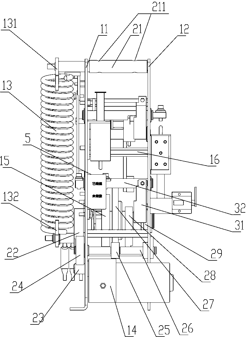
[0031] as attached Figure 1-7 As shown, in this embodiment, an assembled spring operating mechanism includes a left splint 11, a right splint 12, and an energy storage transmission assembly arranged on a frame composed of the left splint 11 and the right splint 12, and the closing The transmission assembly, the opening transmission assembly, the output crank arm 17 and the closing spring 13; wherein the energy storage transmission assembly is arranged in the middle and lower part of the frame; the closing transmission assembly is arranged in the middle of the frame, the opening transmission assembly is arranged in the upper part of the frame, and the output crank The arm 17 is set between the closing transmission assembly and the opening transmission assembly, wherein the frame is connected by the left splint 11, the right splint 12 and the positioning installation shaft 21 p...


PUM


Abstract

The invention relates to the field of a power switch operating mechanism, and particularly to an assembled spring operating mechanism. The assembled spring operating mechanism comprises a left clamping plate, a right clamping plate, an energy storage transmission assembly, a closing transmission assembly, an opening transmission assembly, an output connecting lever and a closing spring, wherein the energy storage transmission assembly, the closing transmission assembly, the opening transmission assembly, the output connecting lever and the closing spring are arranged on a frame which is composed of the left clamping plate and the right clamping plate. The assembled spring operating mechanism has advantages of small space, compact and reasonable structure, and small size. A transmission control mechanism, a closing control transmission mechanism and an opening control transmission mechanism are laid at middle rigid stable positions of the operating mechanism from bottom to top, therebyrealizing sufficient space utilization in a height direction, and improving reliability of the operating mechanism. because a decomposing type structure is adopted, the main components are mounted between the left clamping plate and the right clamping plate and the left end and the right end, thereby effectively ensuring high assembling fixing precision between the components. Because a fixing pinand fixing thread fastening mode is adopted, a purpose of supplying a detachable operating mechanism with advantages of high detachment speed, high reliability and high stability is realized.

Description

technical field [0001] The invention relates to the field of operating mechanisms of electric switches, in particular to an assembled spring operating mechanism. Background technique [0002] The operating mechanism is the main equipment for high-voltage power transmission and transformation, and is an important part of the high-voltage circuit breaker. The opening and closing operations of the high-voltage circuit breaker are realized by the operating mechanism. The operating mechanism of high-voltage circuit breaker is mainly divided into hydraulic operating mechanism and spring operating mechanism. Since there is no oil leakage problem in the spring operating mechanism, compared with the hydraulic operating mechanism, it has the characteristics of low cost, simple structure and long service life. Therefore it is widely used. [0003] However, the spring operating mechanisms currently used in high-voltage circuit breakers generally use the opening spring and closing sprin...

Claims


Application Information

Patent Timeline
Patent Type & Authority Applications(China)
IPC IPC(8): H01H3/30
CPCH01H3/3015Y02E60/16
Inventor 赵汝佳周晓龙言萍香郭位坤苏楚良梁锦钊
Owner 广东维能电气有限公司
Features
  • R&D
  • Intellectual Property
  • Life Sciences
  • Materials
  • Tech Scout
  • Unparalleled Data Quality
  • Higher Quality Content
  • 60% Fewer Hallucinations
Learn More