Airflow heating device

A technology of airflow heating and heating chamber, which is applied in the field of plastic particle drying and dehumidification equipment, which can solve the problems of high temperature and affecting the working status of heating equipment components, and achieve the effect of efficiently retaining heat

Pending Publication Date: 2018-10-23
诺博特(宁波)智能科技有限公司
View PDF7 Cites 0 Cited by
  • Summary
  • Abstract
  • Description
  • Claims
  • Application Information

AI Technical Summary

Problems solved by technology

For drying and dehumidification equipment, a device for heating the airflow is required, usually a cylinder, and a heater is installed inside the cylinder, so that the airflow enters the heater and then heats it, and then discharges the material outside the cylinder. Heating and drying treatment is carried out, but such a structure will generate a higher temperature on the outer surface of the cylinder during long-term operation, which will affect the working status of other components inside the heating equipment

Method used


Image

  • Airflow heating device
  • Airflow heating device
  • Airflow heating device

Examples


Embodiment 1

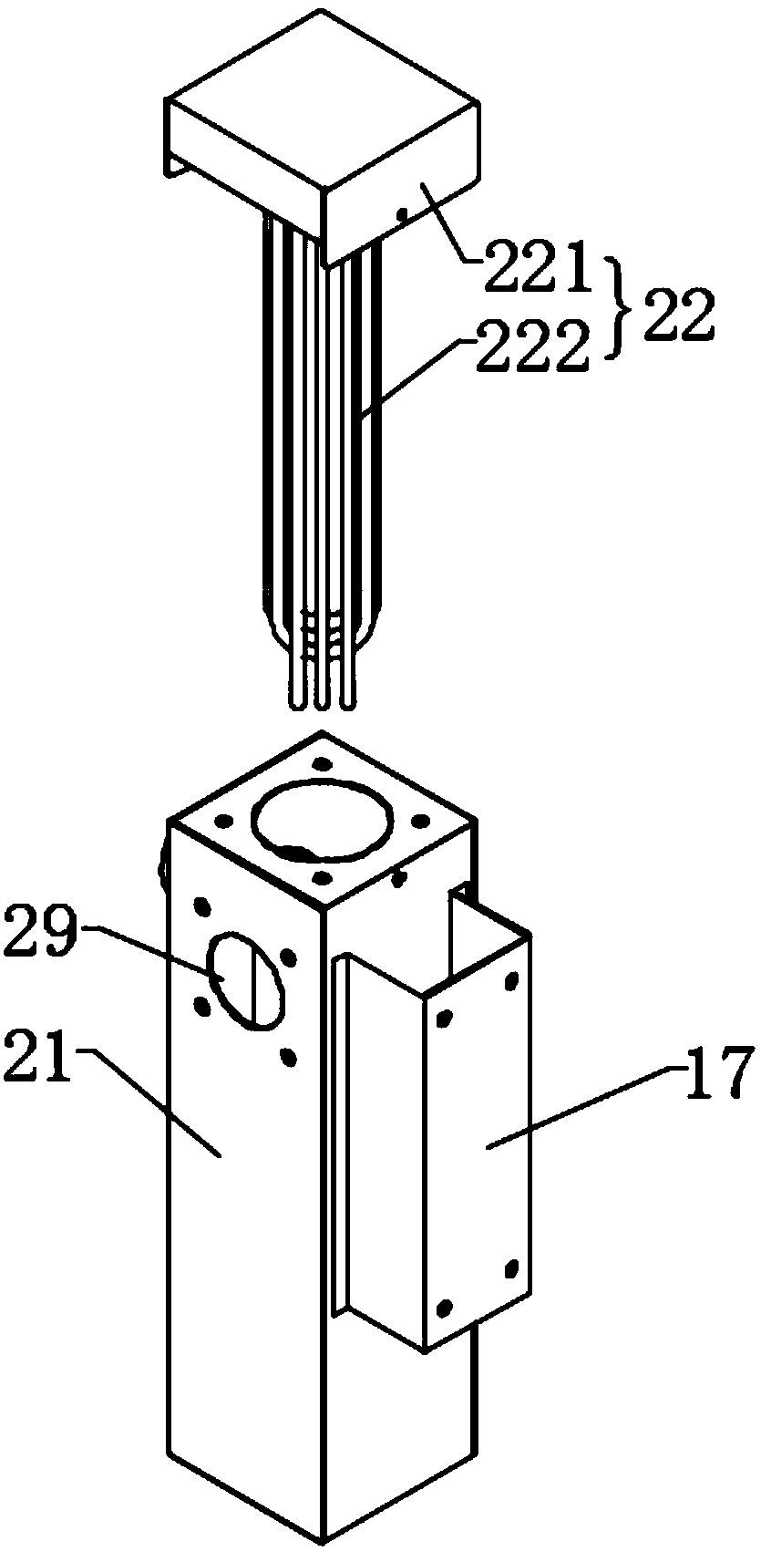
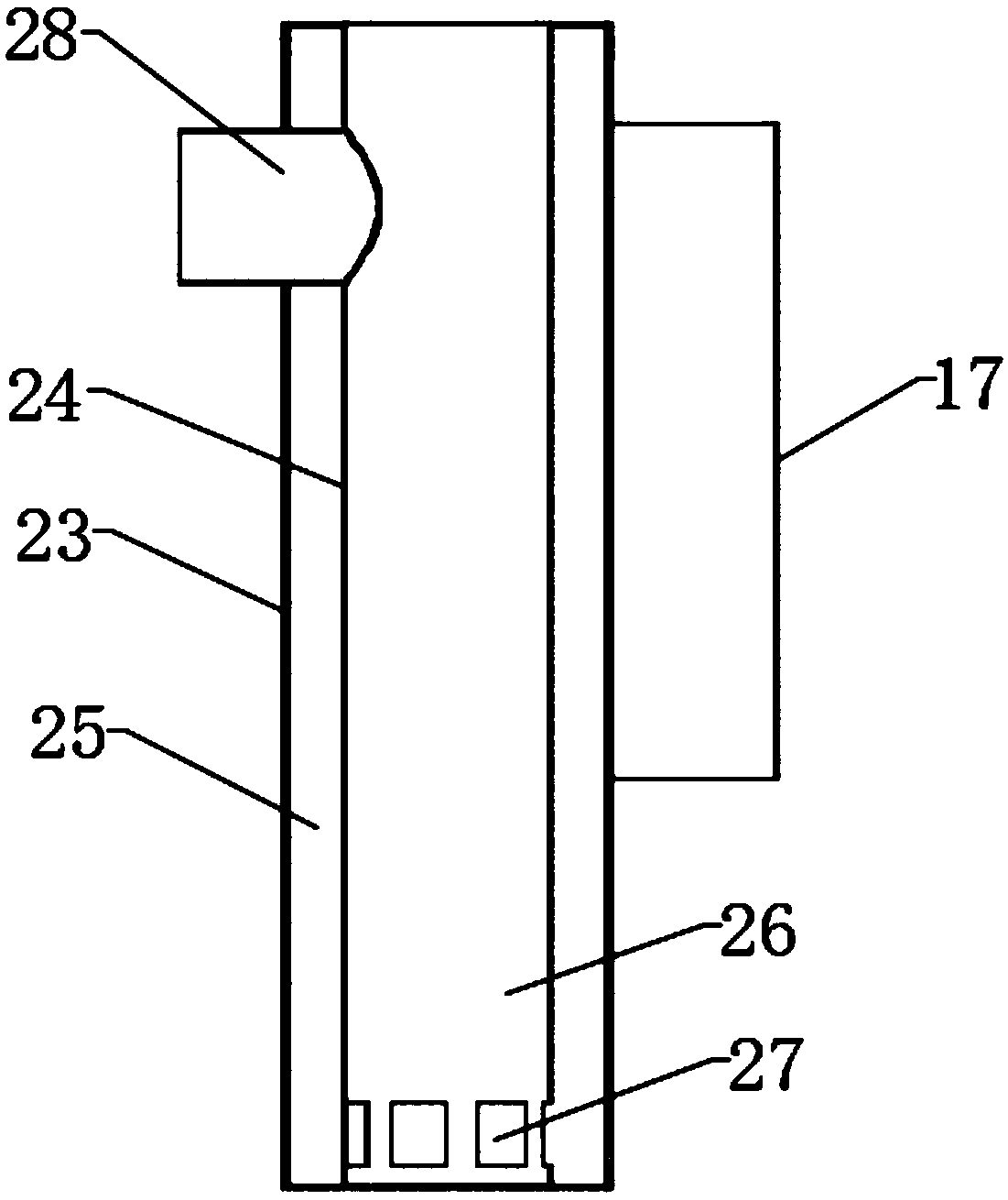
[0025] refer to figure 1 , is an exploded view of the structure of the airflow heating device; combined with figure 2 , is a schematic diagram of the cross-sectional structure of the heating box in the airflow heating device.

[0026] like figure 1 and figure 2 As shown in , the airflow heating device provided by the present invention is used in material drying and dehumidification equipment to heat the airflow passing through it. The airflow heating device includes:

[0027] The heating box 21 comprises an outer casing 23 and an inner casing, and a closed interlayer space 25 is provided between the outer casing 23 and the inner casing 24, a heating cavity 26 is formed in the inner casing 24, and the side wall of the inner casing 24 There is at least one air flow passage 27 connecting the interlayer space 25 and the heating chamber 26 on the top, an air inlet 29 connecting the interlayer space 25 and the outside is provided on the side wall of the outer shell 23, and a si...

Embodiment 2

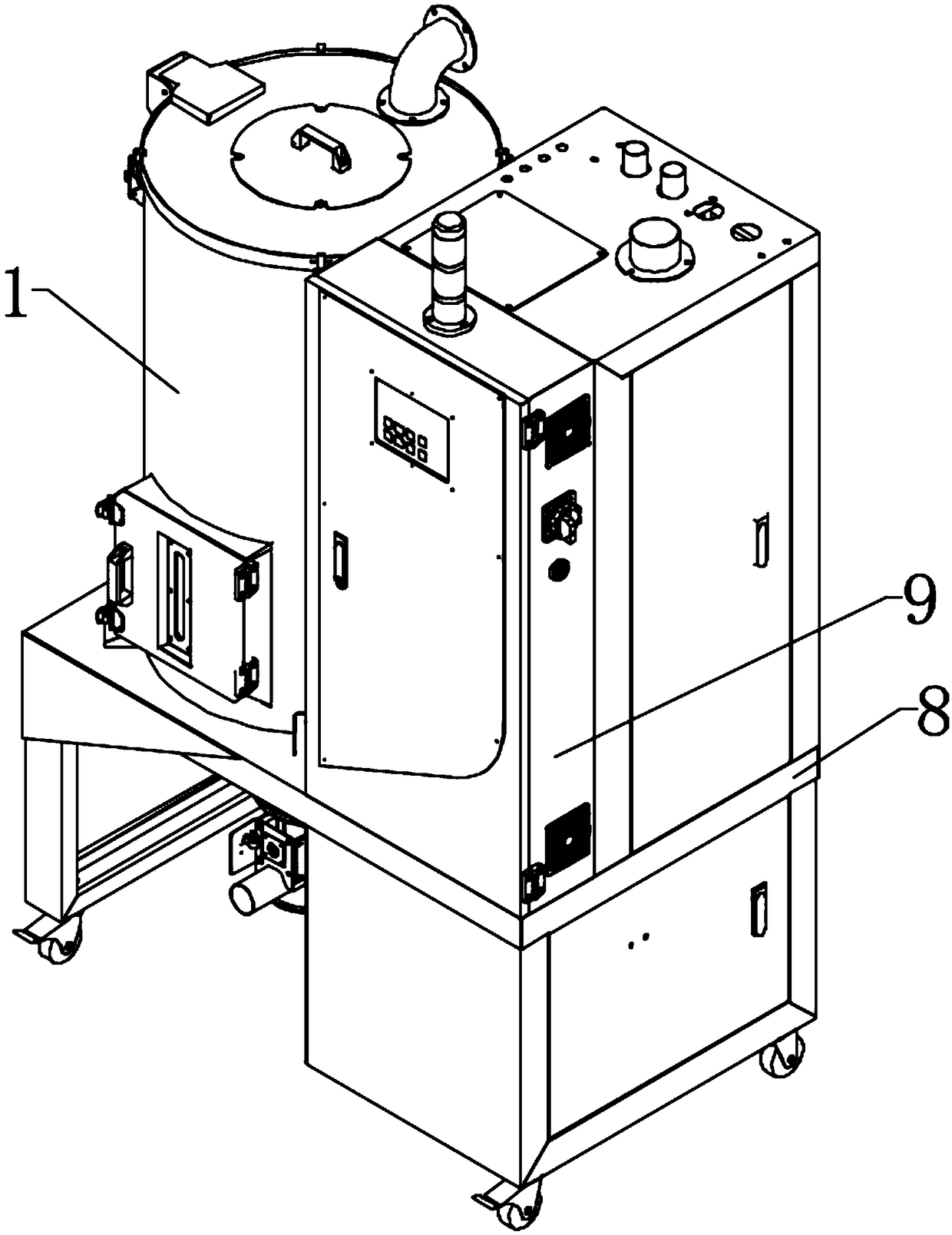
[0032] refer to image 3 , is a three-dimensional view of material drying and dehumidification equipment; combined with Figure 4 , a perspective view of the material drying and dehumidifying equipment after removing the outer casing; and Figure 5 , a perspective view of removing the outer casing and the barrel wall of the drying barrel for the material drying and dehumidifying equipment; and Image 6 , a side view of the material drying and dehumidifying equipment with the outer casing and drying barrel removed; and Figure 7 , is the working principle diagram of the material drying and dehumidification equipment, Figure 7 The direction of the arrow shown in is the direction of gas flow, and in order to show the structure of each component more clearly, in Figure 3 to Figure 6 The pipes used to communicate with the various components are omitted in the figure.

[0033] like Figures 3 to 7 As shown in , the present invention also provides a material drying and dehumid...


PUM


Abstract

The invention discloses an airflow heating device applied to material drying and dehumidification equipment. The airflow heating device comprises a heating box and a heater. The heating box comprisesan outer shell and an inner shell. A closed interlayer space is formed between the outer shell and the inner shell. A heating cavity is formed in the inner shell. The side wall of the inner shell is provided with at least one airflow channel communicating with the interlayer space and the heating cavity. The side wall of the outer shell is provided with an air inlet communicating with the interlayer space and the outside. The side wall of the inner shell is connected with an air outlet pipe. One end of the air outlet pipe communicates with the heating cavity, and the other end of the air outlet pipe penetrates the outer shell to the outside. The heater is arranged on the heating box and used for conducting heating treatment on airflow flowing through the heating cavity. According to the technical scheme of the airflow heating device, the situation that a large amount of heat is prone to being generated in equipment, and the work states of other components are influenced is not likely to happen, and heat can be more efficiently reserved in the heating cavity.

Description

technical field [0001] The invention relates to the technical field of drying and dehumidifying equipment for plastic particles, in particular to an airflow heating device. Background technique [0002] As society's awareness of environmental protection continues to increase, plastic recycling is becoming more and more widespread. The main process is to crush plastic blocks, and then further make granular materials, and then put them into the injection molding machine after drying and dehumidification process. It is reused in the material mouth. For drying and dehumidification equipment, a device for heating the airflow is required, usually a cylinder, and a heater is installed inside the cylinder, so that the airflow enters the heater and then heats it, and then discharges the material outside the cylinder. Heating and drying treatment is carried out, but such a structure will generate a higher temperature on the outer surface of the cylinder during long-term operation, wh...

Claims


Application Information

Patent Timeline
Patent Type & Authority Applications(China)
IPC IPC(8): B29B13/06
CPCB29B13/065
Inventor 吴春晖
Owner 诺博特(宁波)智能科技有限公司
Why Eureka
Try Eureka