

Plastic bottle cap separating device
A separation device and plastic bottle technology, applied in the direction of plastic recycling, recycling technology, etc., can solve the problem of skin abrasion and other problems, achieve the effect of rapid separation and avoid skin abrasion
- Summary
- Abstract
- Description
- Claims
- Application Information
AI Technical Summary
Problems solved by technology
Method used
Image

Examples
Embodiment Construction
[0014] The following is further described in detail through specific implementation methods:
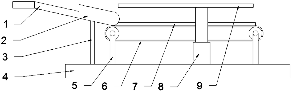
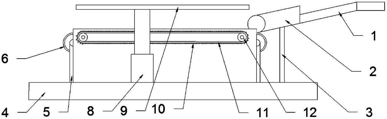
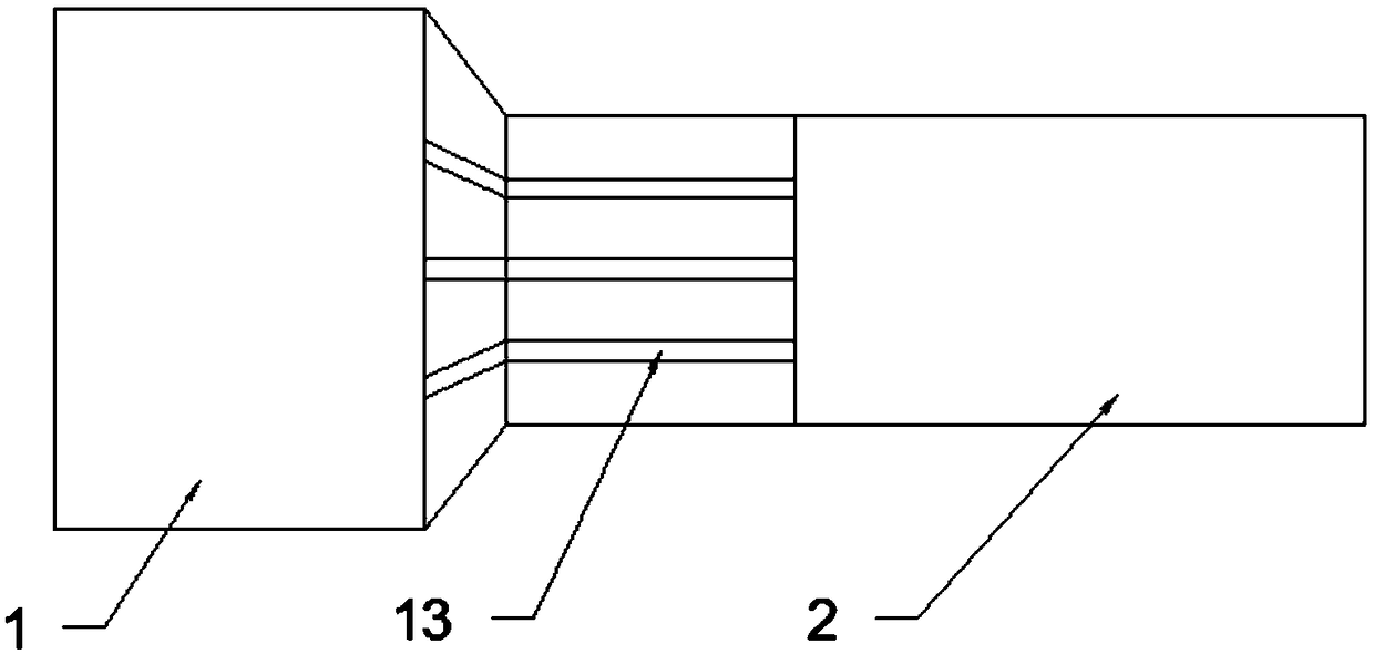
[0015] The reference signs in the accompanying drawings of the description include: guide plate 1, transmission pipe 2, support rod 3, base 4, fixed rod 5, conveyor belt 6, partition plate 7, hydraulic rod 8, pressure plate 9, tooth marks 10, endless belt 11 , roller 12, drainage plate 13.
[0016] The embodiment is basically as attached figure 1 , attached figure 2 And attached image 3 Shown:
[0017] A plastic bottle cap separation device, comprising a base 4, a feeding mechanism and a transmission mechanism, the base 4 is provided with a timing switch (not shown in the figure), the transmission mechanism is located on the base 4, the transmission mechanism includes a conveyor belt 6, the conveyor belt 6 It is electrically connected with the timing switch, and a fixed rod 5 is connected between the conveyor belt 6 and the base 4, and the conveyor belt 6 is in a horizontal sta...
PUM
 Abstract
Description
Claims
Application Information