
washing machine

A technology for washing machines and washing tanks, applied in the field of washing machines, which can solve the problems of increased manufacturing costs, entry of lint, complicated structures, etc., and achieve the effect of a simple structure

Active Publication Date: 2021-01-26
HITACHI GLOBAL LIFE SOLUTIONS INC
View PDF8 Cites 0 Cited by
  • Summary
  • Abstract
  • Description
  • Claims
  • Application Information

AI Technical Summary

Problems solved by technology

[0005] However, since the washing machine described in Patent Document 1 has a structure including a first cover member, a second cover member, etc., the structure may be complicated and the manufacturing cost may be increased.
In addition, there is also a possibility that wire dust or the like enters the engaging portion of the first cover member and the second cover member.
[0006] In addition, in the technique described in Patent Document 1, the engagement portion between the first cover member and the second cover member protrudes outward in the radial direction of the washing tub.
Therefore, since the width (radial width) of the water passage space between the above-mentioned engaging portion and the inner peripheral surface of the washing tub is narrow, there is a possibility that the circulation flow rate of washing water may decrease.

Method used


Image

  • washing machine
  • washing machine
  • washing machine

Examples


Embodiment Construction

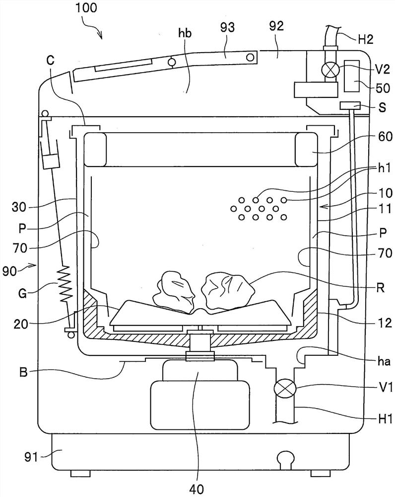
[0023] Hereinafter, as an example, the washing machine 100 (so-called fully automatic washing machine: refer to figure 1 )Be explained.

[0024] "Implementation"

[0025] figure 1 It is a schematic diagram showing the internal structure of washing machine 100 according to the embodiment.

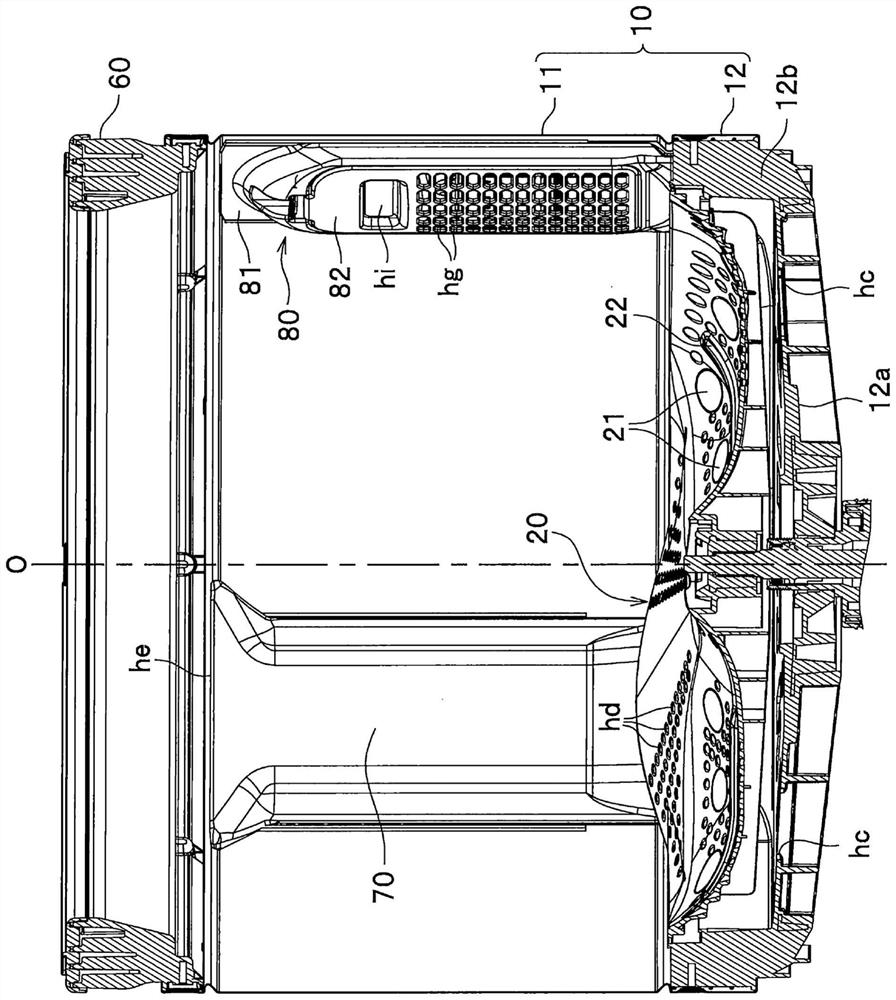
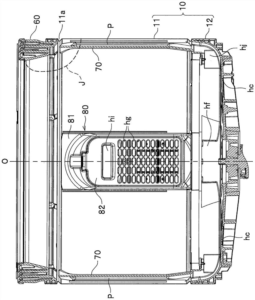
[0026] figure 1 The washing machine 100 shown is equipment for washing clothes, etc., and mainly includes a washing tank 10, a stirring blade 20, an outer tank 30, a driving device 40, a control unit 50, a balance ring 60 (fluid balancer), a circulation flow path member 70, 80, and outer frame 90. also, figure 1 In, another circulation flow path member 80 is not shown (refer to Figure 3A ).

[0027] The washing tub 10 accommodates the laundry R and has a bottomed cylindrical shape. The washing tub 10 includes a cylindrical main body plate 11 (surrounding wall of the washing tub 10 ), and a bottom plate 12 closing the lower portion of the main body plate 11 . The main body plate 11 ...


PUM


Abstract

The present invention provides a washing machine that properly circulates washing water with a simple structure. The washing machine (100) has a cylindrical washing tank (10) with a bottom, a stirring blade provided at the bottom of the washing tank (10), and a plate-shaped circulation flow path member provided on the inner peripheral surface of the washing tank (10). (70), the washing tank (10) is equipped with a convex portion (11a) protruding radially inward near the edge (11b) of the peripheral wall of the washing tank (10), and the convex portion (11a) has a ), the closer to the edge (11b) of the peripheral wall in the axial direction, the shorter the distance from the center axis of the washing tank (10) in the radial direction to the first inclined surface (K1), the nozzle of the circulating flow path member (70) The discharge side extends in the axial direction of the washing tank (10), and the discharge-side front end (70a) of the circulation channel member (70) is located near the convex portion (11a).

Description

technical field [0001] The present invention relates to washing machines. Background technique [0002] There is known a washing machine in which washing water is raised and circulated by rotating an agitating blade provided at the bottom of the washing tub. As such a washing machine, for example, Patent Document 1 describes "a first cover member arranged on the inner peripheral surface side of the main body" of a washing tub and "a Assembly" of the second cover part of the washing machine. [0003] prior art literature [0004] Patent Document 1: Japanese Patent Laid-Open No. 2009-28146 [0005] However, since the washing machine described in Patent Document 1 has a structure including a first cover member, a second cover member, and the like, the structure may become complicated and the manufacturing cost may increase. In addition, there is a possibility that thread waste or the like enters the engagement portion between the first cover member and the second cover memb...

Claims


Application Information

Patent Timeline
Patent Type & Authority Patents(China)
IPC IPC(8): D06F17/06D06F17/04D06F39/08D06F37/26
CPCD06F17/04D06F17/06D06F37/265D06F37/267D06F39/083
Inventor 高中健太曾我丈千叶浩司林佑太朗
Owner HITACHI GLOBAL LIFE SOLUTIONS INC
Learn More