Heat exchanger and exhaust heat recovery device with the heat exchanger

A technology for heat exchangers and exhaust gas, which is applied in the direction of exhaust devices, heat exchangers, exhaust gas treatment, etc., can solve the problems of large quantities and difficulty in miniaturization, and achieve the effect of reducing space

Inactive Publication Date: 2019-01-15
SANGO CO LTD
View PDF7 Cites 0 Cited by
  • Summary
  • Abstract
  • Description
  • Claims
  • Application Information

AI Technical Summary

Problems solved by technology

[0021] On the other hand, the basic structure of the heat exchanger disclosed in Patent Document 6 is different from the above-mentioned heat exchangers in that the "intake cone" and "air outlet cone" of separate parts are not provided, but their large valve devices (valve) are included. body) installed on the main body, it may not be able to meet the requirements of miniaturization
That is, although the structure related to heat exchange in Patent Document 6 is substantially the same as that of the above-mentioned heat exchangers in which the cooling medium passes through the exhaust gas, it is large and complicated in relation to the above-mentioned valve device. structure, requires a large number of parts, so miniaturization is not easy

Method used


Image

  • Heat exchanger and exhaust heat recovery device with the heat exchanger
  • Heat exchanger and exhaust heat recovery device with the heat exchanger
  • Heat exchanger and exhaust heat recovery device with the heat exchanger

Examples


Embodiment Construction

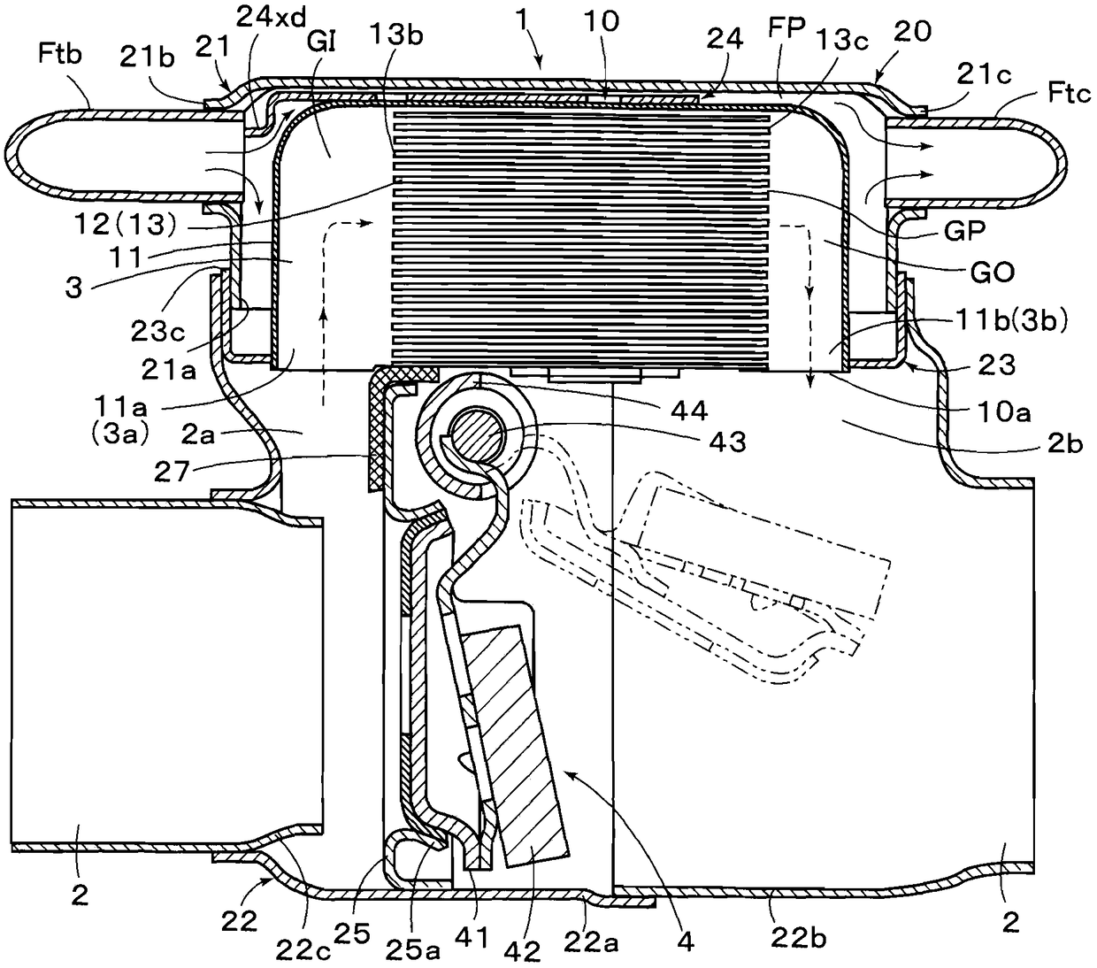
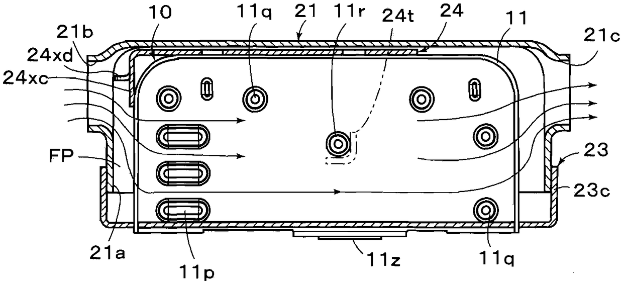
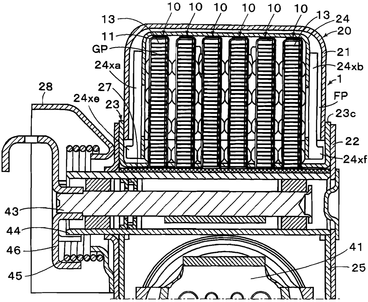
[0074] Preferred embodiments of the present invention will be described below with reference to the drawings. Figure 1 to Figure 3 It is a diagram showing an exhaust heat recovery device including a heat exchanger 1 according to an embodiment of the present invention, and includes a main exhaust flow path 2 for introducing exhaust gas from an internal combustion engine (not shown), and from the main exhaust flow path 2, a detour flow path 3 that branches off and merges with the main exhaust flow path 2, and a heat exchanger 1 that performs heat exchange between exhaust gas passing through the detour flow path 3 and a cooling medium to recover exhaust heat. In the present embodiment, the casing 20 of the exhaust heat recovery device is formed of an upper casing 21 arranged above the main exhaust flow path 2 (in a state mounted on a vehicle) and a lower casing 22 joined thereto. It has a frame shape and is separated in a liquid-tight manner by a sealing member 23 . In addition...


PUM


Abstract

To provide a small-sized exhaust heat recovery device in a heat exchanger for heat exchanging between exhaust gas and cooling medium, enabling much smaller formation to be attained by a less number ofcomponents and further enabling an efficient heat recovery to be carried out. A heat exchanger (1) comprises: a plurality of heat exchanging segments (10) arranged in parallel to each other in a housing; a seal member (23) liquid-tightly connected to the housing to support heat exchanging segments for forming a cooling medium flow passage (FP) at each of clearances of the heat exchanging segmentsadjacent to each other; and a holding tool (24) having a flow regulating part (24xd) for guiding cooling medium introduced from a cooling medium feeding port (21b) to the cooling medium flow passageto hold each of the heat exchanging segments. Each of the heat exchanging segments comprises a casing (11) having an opening only at one surface and having its outside liquid-tightly sealed by the seal member, and a guide member (12) stored in the casing and having a plurality of flow passages (GP) allowing only the exhaust gas flow in a predetermined direction to be flowed.

Description

technical field [0001] The present invention relates to a heat exchanger and an exhaust heat recovery device provided with the heat exchanger, and more particularly to a heat exchanger and an exhaust heat recovery device suitable for internal combustion engines. Background technique [0002] In order to respond to the demand for improved energy efficiency, various industries have taken measures to recover and reuse the heat of the gas exhausted into the atmosphere, that is, the exhaust heat. Especially in the field of automobiles equipped with internal combustion engines, in order to improve the overall thermal efficiency, the exhaust heat recovery device that recovers the heat of the exhaust gas of the internal combustion engine is installed in the exhaust pipe, and the exhaust gas is heated by exchanging heat with the exhaust heat. Cooling medium supply technology that promotes warm-up and improves the performance of heating devices. For example, the following Patent Docu...

Claims


Application Information

Patent Timeline
Patent Type & Authority Applications(China)
IPC IPC(8): F28D21/00F01N5/02
CPCF01N5/02F28D21/0014Y02T10/12F01N2240/02F28D1/0233
Inventor 松浦一成白井理大德田敏哉西野寿海藤优一中野秀则森田庸一
Owner SANGO CO LTD
Why Eureka
Try Eureka