Burner, solid fuel burner and solid fuel boiler, boiler and method of operating the boiler

A solid fuel and burner technology, which is applied in the direction of combustion methods, non-flammable liquid/gas transportation, burners, etc. It can solve the problems of difficult setting of operating parameters and difficulty in fully utilizing the flame stabilization ability of the front end of the flame stabilizer.

Active Publication Date: 2015-11-25
MITSUBISHI HEAVY IND LTD
View PDF15 Cites 0 Cited by
  • Summary
  • Abstract
  • Description
  • Claims
  • Application Information

AI Technical Summary

Problems solved by technology

[0012] In the above-mentioned existing burner, when the fuel gas of pulverized coal and air collides with the flame holder, the air flow is stripped at the rear end of the flame holder, and it is difficult to fully exert the flame stabilizing ability at the front end of the flame holder.
In addition, in the existing boilers, since pulverized coal has moisture or volatile components, only the operating parameters are adjusted based on the operating output of the boiler, and it is difficult to directly set the operating parameters from the properties of the coal.

Method used


Image

  • Burner, solid fuel burner and solid fuel boiler, boiler and method of operating the boiler
  • Burner, solid fuel burner and solid fuel boiler, boiler and method of operating the boiler
  • Burner, solid fuel burner and solid fuel boiler, boiler and method of operating the boiler

Examples


Embodiment 1

[0168] As a conventional burner for a pulverized coal-fired boiler, there is the technology described in the above-mentioned Patent Document 1. In the combustion device described in this patent document 1, by providing a flame stabilizer between the center and the outer peripheral portion of the pulverized coal injection hole (primary flow path), the concentrated stream of pulverized coal can collide with the flame stabilizer, and the Stable low NOx combustion can be performed in a wide load range.

[0169] However, in this existing combustion device, when the fuel gas of pulverized coal and air collides with the flame holder, the air flow is separated at the rear end of the flame holder, and it is difficult to fully exert the flame stabilization at the front end of the flame holder. ability. In addition, in the flow path where the fuel gas of pulverized coal and air circulates, near the flame holder, the cross-sectional area of ​​the flow path becomes smaller due to the arra...

Embodiment 2

[0231] Figure 11 It is a cross-sectional view showing a burner according to Embodiment 2 of the present invention. It should be noted that components having the same functions as those in the above-mentioned embodiments are denoted by the same symbols and detailed description thereof will be omitted.

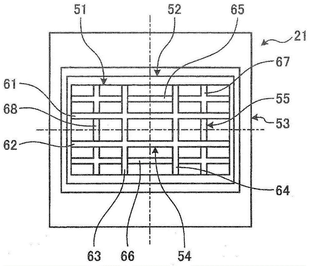
[0232] In the burner of embodiment 2, such as Figure 11 As shown, in the burner 21, a fuel nozzle 51, a secondary air nozzle 52, and a tertiary air nozzle 53 are provided from the center side, and a flame stabilizer 121 is provided. Furthermore, a straightening member 122 is provided between the inner wall surface of the fuel nozzle 51 and the flame stabilizer 121 .

[0233] The flame stabilizer 121 is arranged horizontally at the axial center of the fuel nozzle 51 , and its structure is substantially the same as that of the first flame stabilizers 61 and 62 described in the first embodiment. That is, the flame stabilizer 121 has a widened portion whose width becomes wider ...

Embodiment 3

[0239] Figure 12 It is a cross-sectional view showing a burner according to Embodiment 3 of the present invention. It should be noted that components having the same functions as those in the above-mentioned embodiments are denoted by the same symbols and detailed description thereof will be omitted.

[0240] In the burner of embodiment 3, such as Figure 12 As shown, in the burner 21, a fuel nozzle 51, a secondary air nozzle 52, and a tertiary air nozzle 53 are provided from the center side, and a flame stabilizer 131 is provided. Furthermore, a straightening member 135 is provided inside the flame stabilizer 131 .

[0241] The flame stabilizer 131 is arranged horizontally at the axial center of the fuel nozzle 51 , and two horizontal flame stabilizing members and two vertical flame stabilizing members are arranged to intersect each other. In addition, the rectifying part 135 has: the first rectifying part 136 which is located between each flame stabilizing part in the fl...


PUM


Abstract

Provided are a burner, a burner burning solid fuel, a boiler burning solid fuel, a boiler, and a method for operating the boiler. The burner is provided with a fuel nozzle (51) capable of blowing fuel gas mixed with pulverized coal and primary air. and a secondary air nozzle (52) capable of blowing secondary air from the outside of the fuel nozzle (51), and a flame stabilizer (51) is set on the axial center side of the front end of the fuel nozzle (51), and the fuel nozzle A straightening member (55) is provided between the inner wall surface of (51) and the flame stabilizer (54), thereby realizing proper flow of fuel gas mixed with solid fuel and air.

Description

technical field [0001] The present invention relates to a burner suitable for boilers used to generate steam for power generation or factory use, such as a solid fuel burner and a solid fuel boiler for burning solid fuel (powder fuel) such as pulverized coal. A boiler that combusts solid fuel and air to generate steam and how to operate the boiler. Background technique [0002] For example, a conventional pulverized coal-fired boiler has a hollow furnace installed vertically, and a plurality of burners are arranged along the circumferential direction on the furnace wall and are arranged vertically over multiple layers. The burner is supplied with a mixture of pulverized coal (fuel) and primary air, and is supplied with high-temperature secondary air. The mixture and secondary air are blown into the furnace to form a flame. And can burn in this furnace. Moreover, the furnace is connected to a flue at the upper part, and a superheater, a reheater, an economizer, etc. for rec...

Claims


Application Information

Patent Timeline
Patent Type & Authority Patents(China)
IPC IPC(8): F23D1/00F23C6/04F23L9/02
CPCF23C5/32F23C6/045F23C2201/20F23D1/00F23D2201/101F23D2201/20F23N2221/10F23L9/00F23C6/04F23L9/02F23D1/005F23N3/00F23D2201/10F23D2209/20F23K2203/201
Inventor 松本启吾堂本和宏阿部直文葛西润
Owner MITSUBISHI HEAVY IND LTD
Why Eureka
Try Eureka