Multi-way shock absorbing device for bridge pier

A shock-absorbing device and bridge pier technology, which is applied to bridges, bridge parts, bridge materials, etc., can solve problems such as long reinforcement period, interruption of traffic, and damage to the cap foundation, so as to reduce earthquake resistance requirements, dissipate earthquake energy, and reduce The effect of horizontal displacement

Pending Publication Date: 2018-10-23
林同棪国际工程咨询(中国)有限公司
View PDF0 Cites 6 Cited by
  • Summary
  • Abstract
  • Description
  • Claims
  • Application Information

AI Technical Summary

Problems solved by technology

However, both of these two methods have certain shortcomings: the first method requires the installation of expensive shock-absorbing and isolating supports, and the installation of shock-absorbing and isolating devices requires that there must be enough space between the piers and beams, and traffic must be suspended when replacing , but this method has no obvious shock-absorbing effect on piers with high pier height and high mass; when the second method is implemented, traffic needs to be interrupted. If concrete is used, the poured concrete needs to be cured. The entire reinforcement period is long. If steel pipes are used, the connection performance between steel pipes and concrete is not easy to be guaranteed. Finally, this method will increase the seismic requirements of the cap foundation, which may cause damage to the cap foundation under the action of earthquakes.

Method used


Image

  • Multi-way shock absorbing device for bridge pier
  • Multi-way shock absorbing device for bridge pier
  • Multi-way shock absorbing device for bridge pier

Examples


Embodiment Construction

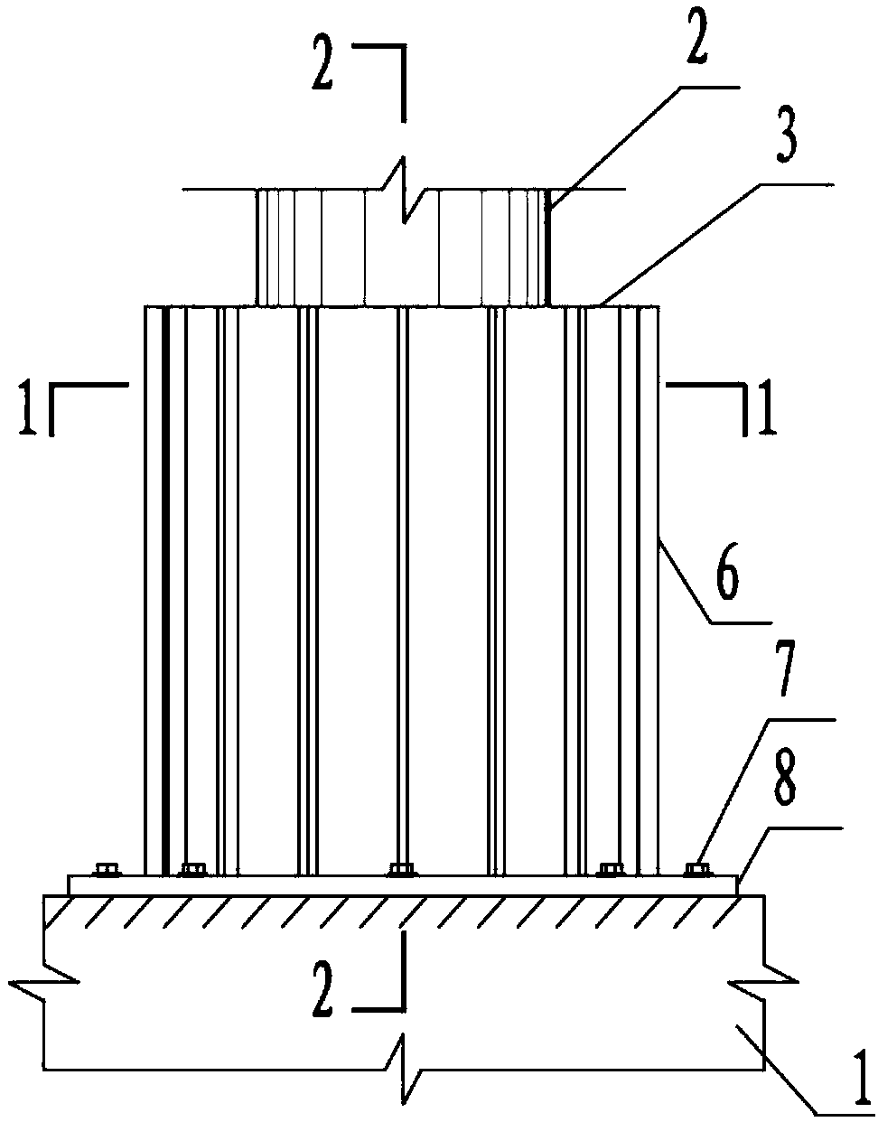
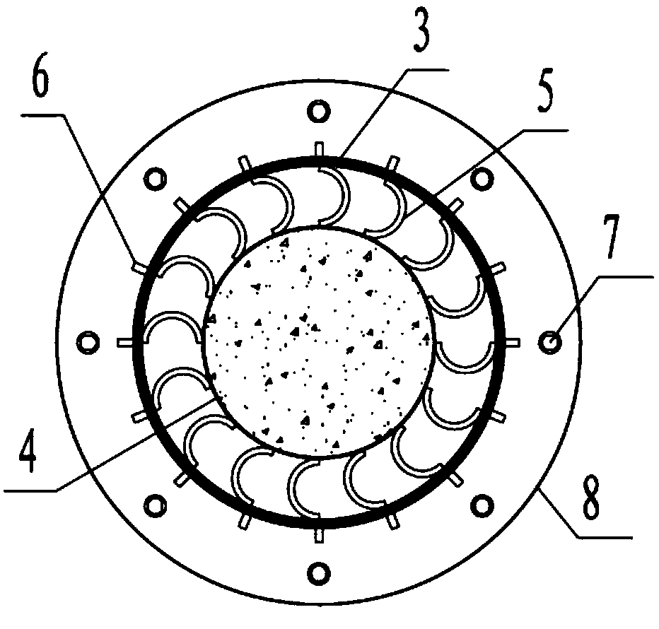
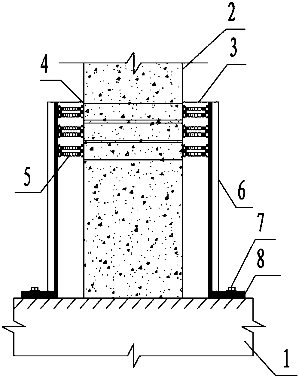
[0021] figure 1 It is a structural schematic diagram of the present invention, figure 2 for figure 1 1-1 Schematic diagram of the cross-sectional structure; image 3 for figure 1 The 2-2 section structure shows; Figure 4 It is a schematic diagram of a partially enlarged structure of the present invention.

[0022] As shown in the figure, the pier multi-directional damping device in this embodiment includes an inner layer connection plate and an outer layer fixed support plate that are detachably arranged on the pier column cap and are arranged along the circumference of the pier column outer surface. Between the inner connecting plate and the outer fixed support plate, there are a plurality of elastoplastic deformation members evenly distributed radially along the cross-section of the pier column; the inner connecting plate 4 is arranged on the outer surface of the pier column 2. 2. The inner layer connecting plate 4 can be directly sleeved on the surface of the pier c...


PUM


Abstract

The invention discloses a multi-way shock absorbing device for a bridge pier. The multi-way shock absorbing device for the bridge pier comprises an inner layer connecting plate and an outer layer fixing-supporting plate. The inner layer connecting plate and the outer layer fixing-supporting plate are detachably arranged on a pier column bearing platform and are arranged in the circumferential direction of the outer surface of a pier column. A plurality of elastic-plastic deformational components are uniformly distributed between the inner layer connecting layer and the outer layer fixing-supporting plate in the radial direction of the pier column section. Under the condition of usual using, the shock absorbing device keeps elastic, and normal operation of the bridge pier is not affected. Under the action of seismic loads, horizontal displacement of the bridge pier body occurs. When the bridge pier is overly displaced, the shock absorbing device yields, and an outer support device stillstays elastic. The shock absorbing device conducts reciprocation hysteretic energy dissipation through elastic-plastic deformation, so that the earthquake energy is dissipated, and the bridge pier horizontal displacement is reduced. The multi-way shock absorbing device of the column bridge pier is low in price, can be prefabricated in a factory, and can be assembled quickly in a construction sitewithout affecting normal using of the bridge. Moreover, the multi-way shock absorbing is convenient to replace after an earthquake, and can also be used as an anti-collision device of the pier bottom.

Description

technical field [0001] The invention relates to the field of bridges, in particular to a multi-directional damping device for bridge piers. Background technique [0002] Small and medium-span beam bridges are widely used in my country and are an extremely important part of my country's increasingly developed road traffic network. Cylindrical pier is one of the substructure forms commonly used in this type of bridge. The cylindrical pier is consolidated with the cap, and the load transmitted from the upper structure of the bridge is finally transmitted to the foundation through the cylindrical pier, so that the entire bridge structure can maintain normal use. At present, my country's current "Seismic Design Rules for Highway Bridges" and "Code for Seismic Design of Urban Bridges" stipulate that small and medium-span girder bridges are required to maintain elasticity under E1 earthquakes, damage is allowed under E2 earthquakes, and plastic hinges are allowed on bridge piers. ...

Claims


Application Information

Patent Timeline
Patent Type & Authority Applications(China)
IPC IPC(8): E01D19/02E01D101/30
CPCE01D19/02E01D2101/30
Inventor 郭葳刘雪山刘安双陈晓虎
Owner 林同棪国际工程咨询(中国)有限公司
Why Eureka
Try Eureka