Anti-glare wear-resistant cover plate and manufacturing method thereof

A manufacturing method and cover plate technology, which can be applied to optical components, optics, instruments, etc., can solve problems such as anti-fouling failure, wear, and impact on anti-glare, so as to achieve good anti-wear ability and improve the effect of anti-wear ability

A manufacturing method and cover plate technology, which can be applied to optical components, optics, instruments, etc., can solve problems such as anti-fouling failure, wear, and impact on anti-glare, so as to achieve good anti-wear ability and improve the effect of anti-wear ability

CN108693573AInactive Publication Date: 2018-10-23HENGHAO TECH CO LTD

Image

  • Anti-glare wear-resistant cover plate and manufacturing method thereof
  • Anti-glare wear-resistant cover plate and manufacturing method thereof
  • Anti-glare wear-resistant cover plate and manufacturing method thereof

Examples


Embodiment Construction

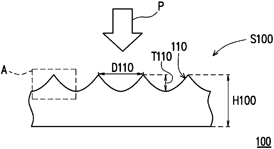
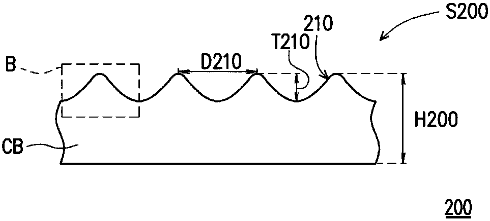
[0039] Figure 1A and Figure 1B It is a partial cross-sectional schematic diagram of a manufacturing process of the manufacturing method of the anti-glare and wear-resistant cover plate of the present invention. Please refer to Figure 1A , Provide anti-glare cover 100. The anti-glare cover 100 has a plurality of microstructures 110 located on the anti-glare side S100 of the anti-glare cover 100. The plurality of microstructures 110 are adapted to scatter the light beam irradiated to the anti-glare side S100 of the anti-glare cover plate 100 to achieve an anti-glare effect. In this embodiment, the anti-glare cover 100 is a glass cover, and the glass transition temperature of the anti-glare cover 100 is T. The plurality of microstructures 110 are formed, for example, by chemically etching a glass cover plate. Compared to forming the anti-glare cover sheet by surface sticking film or vacuum coating, the anti-glare cover sheet 100 formed by etching may have a relatively thin thic...


PUM


Abstract

An anti-glare wear-resistant cover plate including a cover plate body and a manufacturing method thereof are provided. The cover plate body has a plurality of microstructures located at an anti-glareside of the cover plate body. The plurality of microstructures has a plurality of top surfaces, wherein a change in slope of a section line of each of the plurality of top surfaces on a reference plane perpendicular to the cover plate body is continuous. A manufacturing method of the anti-glare wear-resistant cover plate is also provided.

Description

Technical field [0001] The invention relates to a cover plate and a manufacturing method thereof, and in particular to an anti-glare and wear-resistant cover plate and a manufacturing method thereof. Background technique [0002] In response to the anti-glare function of the product, an anti-glare layer is often provided on the surface of the electrical device. In addition, to further have the anti-smudge effect, an anti-smudge functional layer can be provided on the anti-glare functional layer. However, the surface of the electrical device is prone to wear due to contact and use, which in turn leads to the failure of the anti-fouling function, and even affects the anti-glare function. Summary of the invention [0003] The invention provides an anti-glare and wear-resistant cover plate, which has good abrasion resistance. [0004] The invention provides a method for manufacturing an anti-glare and wear-resistant cover plate, which can effectively improve the anti-wear ability of t...

Claims


Application Information

Patent Timeline
23 Oct 2018
Publication
CN108693573A
IPC
G02B1/14; G02B1/10; G02B27/00
CPC
G02B1/10; G02B27/0006; G02B1/14; G02B5/0215; G02B5/0268; G02B5/0294; G02B1/18
Inventors
ι™ˆδΏŠθ£; ι™ˆη…œδΈœ