
Rotary objective table for multi-station precise operation, and control method

A rotating stage and multi-station technology, applied in piezoelectric effect/electrostrictive or magnetostrictive motors, electrical components, generators/motors, etc. Affect the movement and positioning accuracy, and the processing accuracy is extremely high, so as to achieve the effect of improving output performance, convenient control, and stable operation

Active Publication Date: 2018-10-23
NORTHEASTERN UNIV
View PDF8 Cites 9 Cited by
  • Summary
  • Abstract
  • Description
  • Claims
  • Application Information

AI Technical Summary

Problems solved by technology

The traditional stage, which is driven by a motor and driven by precision screw nut pairs, precision spiral wedges, etc., has a large gap and friction, the structure is not compact enough, there are reasons such as crawling, multi-link transmission, etc., which cannot meet the modern requirements. Technical Requirements for Precision Operations
Most of the rotary positioning devices designed with new driving methods can only rotate at a certain angle and cannot achieve 360° forward and reverse rotation, and some mechanisms that realize 360° forward and reverse rotation through the principle of inchworm movement also have insufficient clamping displacement to affect processing. High precision requirements, high motion friction and other defects, and its rough control strategy completely ignores the nonlinear characteristics of the piezoelectric actuator during motion. Although the motion of the stage is realized, it seriously affects the motion and positioning accuracy.

Method used


Image

  • Rotary objective table for multi-station precise operation, and control method
  • Rotary objective table for multi-station precise operation, and control method
  • Rotary objective table for multi-station precise operation, and control method

Examples


Embodiment Construction

[0038] Refer to attached Figures 1 to 9 The rotary stage and control method for multi-station precision operation of the present invention are described in detail.

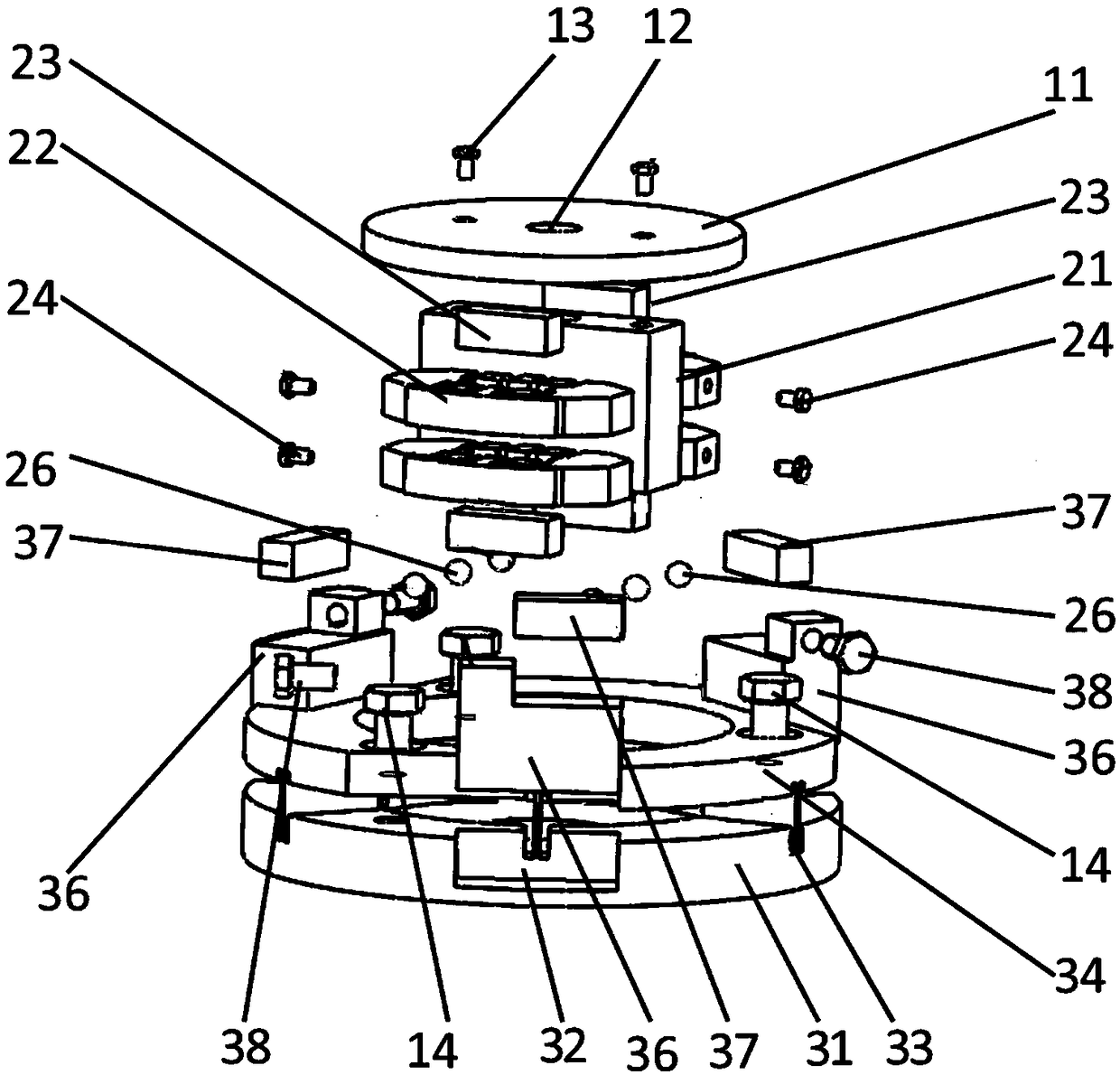
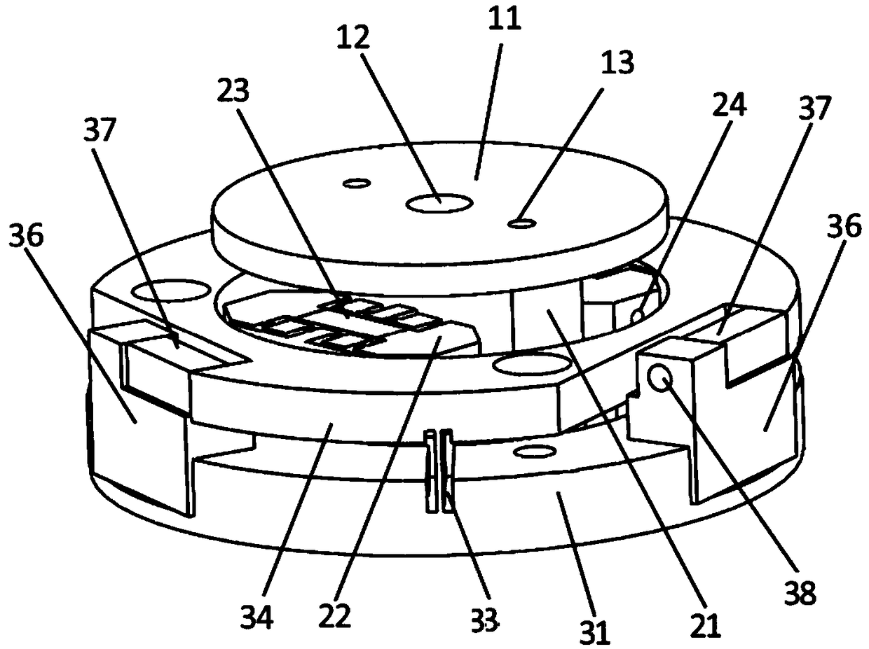
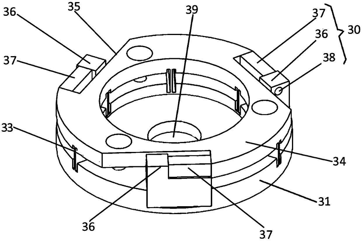
[0039]The rotary stage and control method for multi-station precision operation of the present invention belong to the field of precision operation, can be applied to the rotation positioning of multi-station precision operation, and can be used for precision optics, precision machining, micromanipulation, micro-clamping, Micromechanical performance testing and other fields. The rotating stage includes: a fixing mechanism, a moving mechanism and a loading plane 11 . The moving mechanism is assembled in the fixing mechanism through a clearance fit, and the fixing mechanism is provided with a plurality of piezoelectric stack drive units 30, and the plurality of piezoelectric stack driving units 30 generate axial displacement after being energized to drive the moving mechanism For rotation, the loading plane 11 is...


PUM


Abstract

The invention discloses a rotary objective table for a multi-station precise operation, and a control method. The rotary objective table consists of three parts: a fixed mechanism, a moving mechanismand a carrying plane. A piezoelectric stack is taken as a driver, and the stepping rotation is achieved through the bionic inchworm-like movement principles. The fixed mechanism comprises an upper layer and a lower layer, which are connected through a rectangular flexible hinge. Three groups of drive units are uniformly distributed on an external diameter of the lower layer. The moving mechanism comprises an upper layer and a lower layer, and the upper and lower layers are respectively in clearance fit with the upper and lower layers of the fixed mechanism in an assembly process. Each layer ofthe moving mechanism is designed to have a clamping unit which takes a bridge-type micro-displacement amplifying mechanism as the main body. After the driving through the piezoelectric stack, the size of the diameter of a moving part is increased, and the clearance fit between the moving mechanism and the fixed mechanism is converted into interference fit for achieving the clamping. In order to achieve the bionic inchworm-like movement principles, a strict time sequence control signal is designed, and the compensation for a control signal is carried out according to the nonlinearity of the drive unit. Therefore, the rotary objective table is compact in structure, is quick in response, is high in positioning precision, and is large in stroke.

Description

technical field [0001] The invention relates to the field of precision machinery and precision operation, in particular to a rotary stage and a control method for multi-station precision operation. Background technique [0002] With the development of modern science and technology, the field of human research has expanded to the microscopic world. In order to improve work efficiency, multi-station precision operations have gradually become a research hotspot. The stage with precise rotation and positioning capability is the basis of multi-station precision operation, and it is increasingly demanded in the fields of microelectronics, life science, pharmaceutical chemistry, semiconductor, optics, ultra-precision machinery and its manufacturing. The traditional stage, which is driven by a motor and driven by a precision screw nut pair, a precision screw wedge, etc., has a large gap and friction, the structure is not compact enough, there are reasons such as crawling and multi-l...

Claims


Application Information

Patent Timeline
IPC IPC(8): H02N2/12H02N2/14
CPCH02N2/12H02N2/14
Inventor 郝丽娜车鸿鹏高金海
Owner NORTHEASTERN UNIV
Learn More