Moving iron receiver

A receiver and moving iron technology, applied in the field of receivers, can solve the problems of lateral positioning of the iron and the like, and achieve the effect of reducing the accuracy requirement and improving the production cost and production efficiency.

Inactive Publication Date: 2018-10-23
SHENZHEN BELLSING ACOUSTIC TECH CO LTD
View PDF4 Cites 0 Cited by
  • Summary
  • Abstract
  • Description
  • Claims
  • Application Information

AI Technical Summary

Problems solved by technology

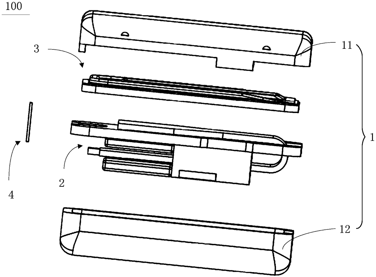
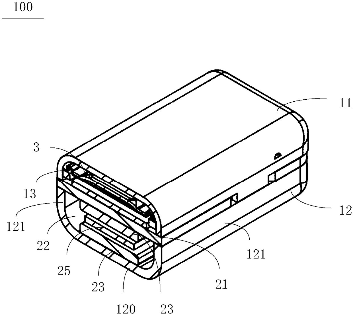
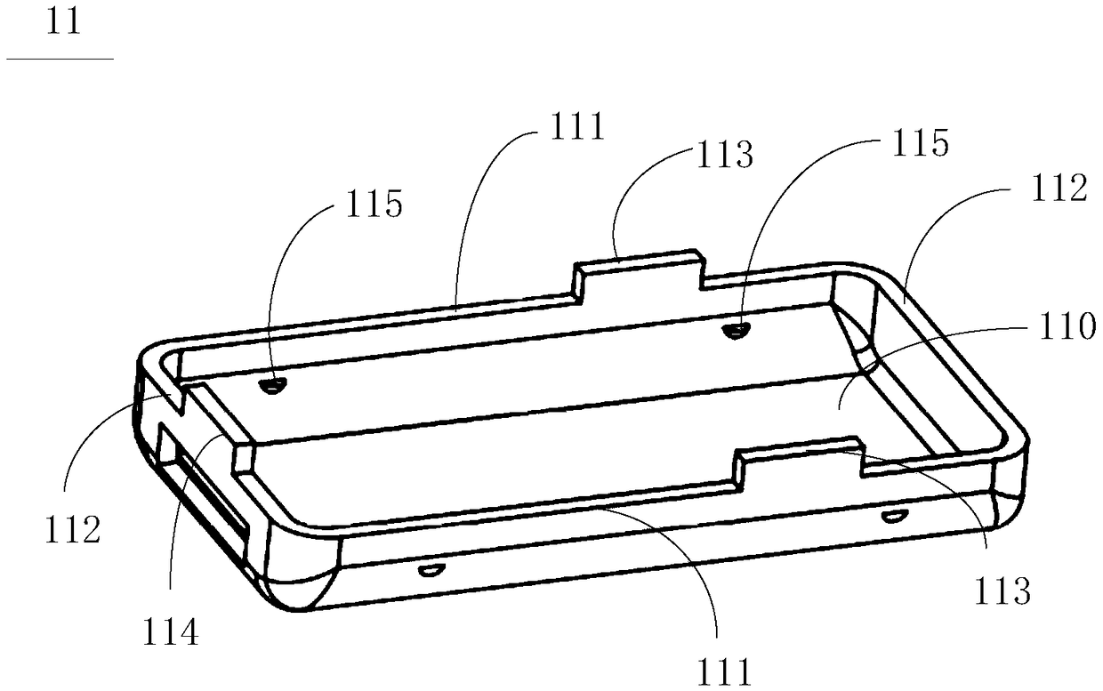
[0006] In order to solve the problem of the lateral positioning of the collar iron in the moving iron receiver, the invention provides a moving iron receiver comprising a laterally positioned collar iron

Method used


Image

  • Moving iron receiver
  • Moving iron receiver
  • Moving iron receiver

Examples


Embodiment Construction

[0030] In order to facilitate the understanding of the present invention, the present invention will be described in more detail below in conjunction with the accompanying drawings and specific embodiments. It should be noted that when an element is said to be "fixed" to another element, it may be directly on the other element, or there may be one or more intervening elements therebetween. When an element is referred to as being "snaps into" another element, it can be directly snapped onto the other element or one or more intervening elements may be present therebetween. The terms "upper", "lower", "left", "right" and similar expressions are used in this specification for the purpose of description only.

[0031] Unless otherwise defined, all technical and scientific terms used in this specification have the same meaning as commonly understood by one of ordinary skill in the technical field of the invention. Terms used in the description of the present invention are only for ...


PUM


Abstract

The embodiment of the invention relates to the field of receivers, and provides a moving iron receiver. The moving iron receiver comprises a shell and a motor component, wherein the shell comprises anupper shell and a lower shell, the upper shell and the lower shell are fastened to each other to form an accommodating space, and one of the upper shell and the lower shell extends to the other one to form a clamping part; and the motor component is accommodated in the accommodating space, the motor component comprises jaw iron, the jaw iron is in the shape of a flat plate, the outer side of thejaw iron is provided with a clamping groove, the jaw iron is located between the upper shell and the lower shell, and the clamping groove is accommodated in the clamping part. Thereby, the lateral positioning of the jaw iron can be achieved, the requirements for the accuracy of an assembly fixture when assembling the jaw iron can be reduced, the production cost of the moving iron receiver can be reduced, and the production efficiency of the moving iron receiver can be improved.

Description

technical field [0001] The invention relates to the technical field of receivers, in particular to a moving iron receiver. Background technique [0002] A moving iron receiver, also known as a moving iron horn, is a sound-generating component. It is designed on the basis of the reed speaker, and uses high-precision micro-processing technology. Through the miniaturization of parts and the use of new materials, it maintains its high acoustic-electric conversion rate and overcomes the frequency response and distortion of acoustic-electric conversion. big deficiency. Due to its small size, low power consumption, high output and other characteristics, it is widely used in hearing aids, covert communication, high-fidelity earphones and other fields. [0003] The existing moving iron receiver mainly includes a casing composed of an upper casing and a lower casing, a motor assembly and a diaphragm assembly. The motor assembly generally includes a ring iron in a closed ring shape, ...

Claims


Application Information

Patent Timeline
IPC IPC(8): H04R11/04
CPCH04R11/04
Inventor 陈斌
Owner SHENZHEN BELLSING ACOUSTIC TECH CO LTD
Why Eureka
Try Eureka