Supercharge Your Innovation With Domain-Expert AI Agents!

Spray gun cups, receptacles, and methods of use

A receiver and spray gun technology, which is applied to instruments, spray devices, liquid level indicators, etc., can solve problems such as the difficulty of painters, and achieve the effect of easy use and low manufacturing cost.

Inactive Publication Date: 2018-10-23
3M INNOVATIVE PROPERTIES CO
View PDF8 Cites 0 Cited by
  • Summary
  • Abstract
  • Description
  • Claims
  • Application Information

AI Technical Summary

Problems solved by technology

This coating of paint can cause real difficulties for painters

Method used


Image

  • Spray gun cups, receptacles, and methods of use
  • Spray gun cups, receptacles, and methods of use
  • Spray gun cups, receptacles, and methods of use

Examples


Embodiment Construction

[0208] It should be noted that in the drawings, some elements may be present in identical or equivalent multiples; in such a case, one or more representative elements may be designated by reference numerals only, it being understood that such reference numerals The same applies to all such elements.

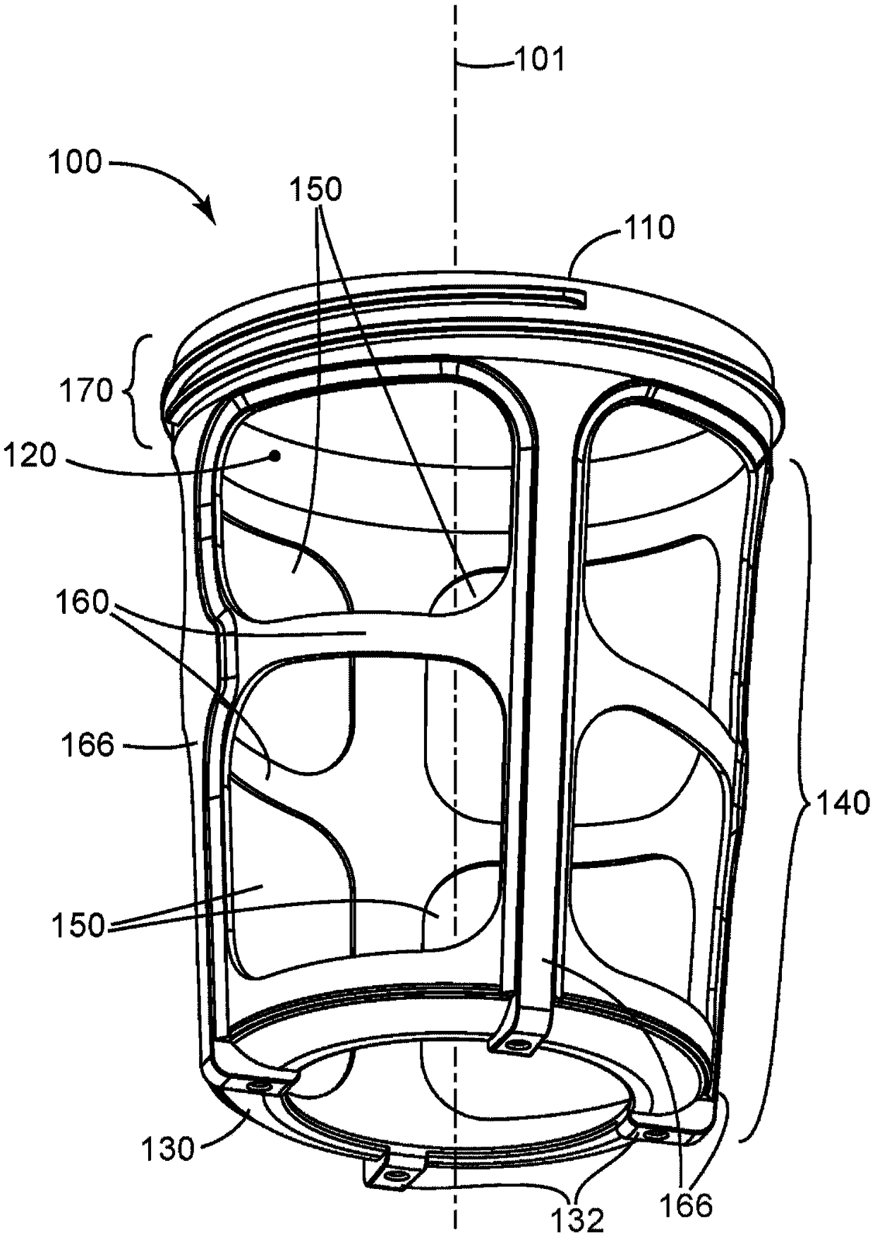
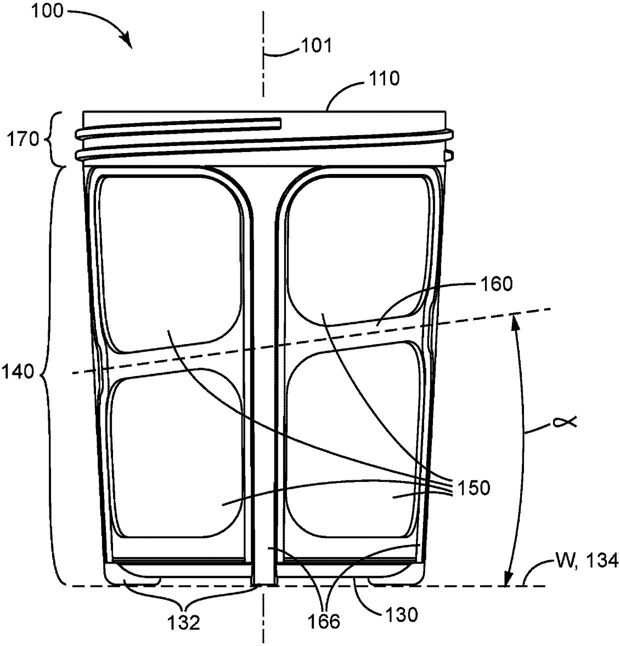
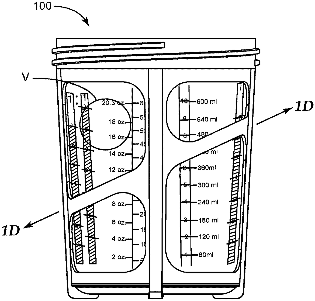
[0209] Figure 1A and Figure 1B An exemplary embodiment of a spray gun cup receptacle 100 according to the present invention is shown. The spray gun cup receiver 100 includes an open end 110 that provides access to an interior cavity 120 . Opposite the open end 110 is a base end 130 . As shown, base end 130 includes a substantially flat configuration with optional feet 132, allowing the base to be stably placed directly on a flat work surface W ( Figure 1A not shown in ). The number, shape and arrangement of the feet 132 can be varied as desired. In some embodiments, the base end 130 is not flat by itself, but can be held stationary on a work surface as described above by m...


PUM


Abstract

A spray gun cup receptacle is disclosed comprising an open end for receiving a liner within a cavity and a base end opposite the open end. The sidewall comprises at least one aperture through which the cavity is visible from outside the spray gun cup receptacle. The apertures are divided one above the other by a brace member, at least a portion of which is disposed at a brace member angle [alpha]relative to the base plane. Also disclosed are receptacles comprising one or more tactile feedback members positioned adjacent an aperture.

Description

Background technique [0001] Liquid spray guns are often used to spray coatings such as stains, primers, paints, sealers, etc. onto surfaces. It is known to provide a liquid spray gun with a paint cup containing the liquid to be sprayed. There is a need for improved paint cups, parts for paint cups, and methods of use thereof. Contents of the invention [0002] It has been observed that paint cups and their components have a tendency to become coated in paint when used in their typical environment (eg, in the mixing room of an automotive collision repair shop). Such coatings of paint can cause practical difficulties for the painter. For example, even though paint cups may be clear when purchased (to allow viewing of the cup's contents), viewing the contents eventually becomes difficult or impossible due to the buildup of dried paint. In particular, to facilitate the correctly measured mixing of the components of paint or other substances, clear paint cup systems often incl...

Claims


Application Information

Patent Timeline
Patent Type & Authority Applications(China)
IPC IPC(8): B05B7/24B05B9/08
CPCB05B7/2402B05B9/0894B05B7/2408B05B7/2478B05B7/2481B44D3/14G01F23/02B05B15/60B05B9/0855B05B9/0838
Inventor 安娜·M·赫格达赫尔史蒂芬·C·P·约瑟夫多米尼克·M·皮泰拉埃里克·O·纳亚里博
Owner 3M INNOVATIVE PROPERTIES CO
Features
  • R&D
  • Intellectual Property
  • Life Sciences
  • Materials
  • Tech Scout
  • Unparalleled Data Quality
  • Higher Quality Content
  • 60% Fewer Hallucinations
Learn More