
Method for manufacturing glass container

A technology for glass containers and manufacturing methods, applied in glass manufacturing equipment, glass molding, glass blowing molds, etc., can solve problems such as inability to form large bubbles, and achieve stable molding effects

Inactive Publication Date: 2018-10-23
KOA GLASS CO LTD
View PDF9 Cites 3 Cited by
  • Summary
  • Abstract
  • Description
  • Claims
  • Application Information

AI Technical Summary

Problems solved by technology

[0025] Therefore, since the three-dimensional shape of the plunger must be basically columnar, the shape of the internal space that can be molded is also basically limited to columnar, so there is a problem that the internal space of a characteristic shape such as a large bubble shape cannot be molded.

Method used


Image

  • Method for manufacturing glass container
  • Method for manufacturing glass container
  • Method for manufacturing glass container

Examples


Embodiment 1

[0304] 1. Manufacture of glass containers

[0305] (1) Process (A)

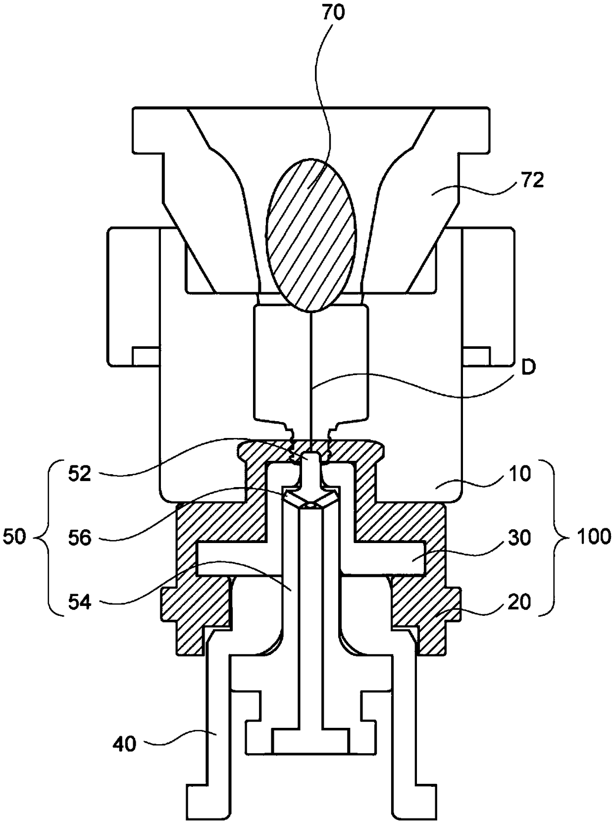
[0306] Such as figure 1 As shown, after fitting the funnel into the molding die, 55 g (950° C.) of soda-lime glass blank was thrown into the molding die through the funnel.

[0307] (2) Process (B)

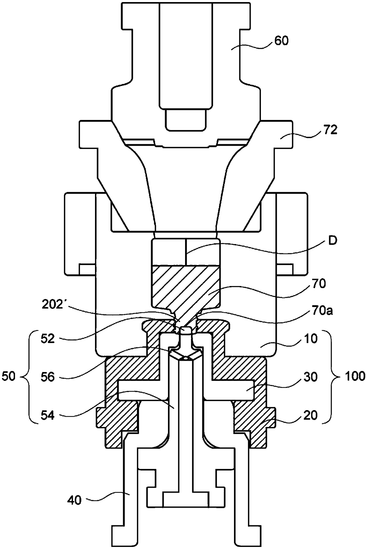
[0308] Next, if figure 2 As shown, the air is blown into the molding die through the funnel, and after the glass blank is brought into contact with the plunger arranged on the side opposite to the side where the funnel is fitted, the plunger is kept away from the glass blank, and the glass blank is formed on the surface of the glass blank. Recess (circular in plan view, 5.7 mm in diameter, 3.5 mm in depth).

[0309] (3) Process (C)

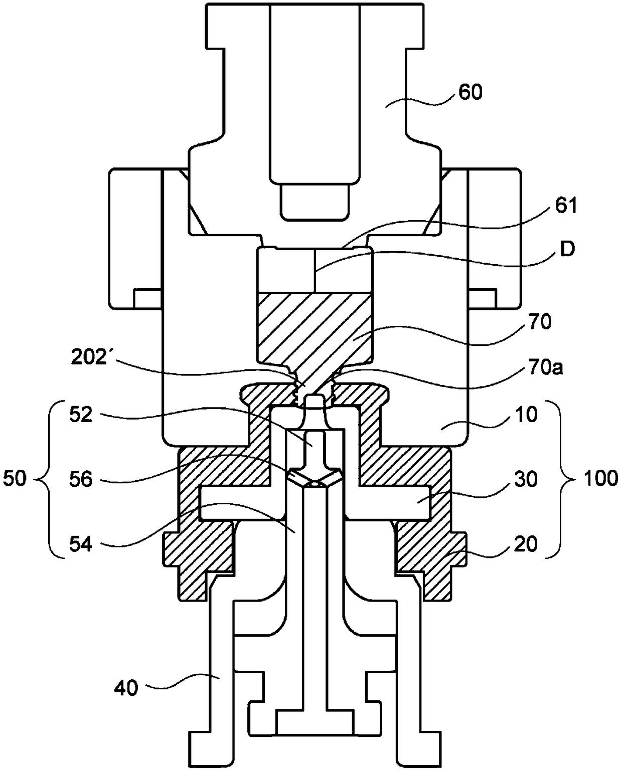
[0310] Next, if image 3 As shown, after removing the funnel from the molding die, fit the baffle into the molding die.

[0311] (4) Process (D)

[0312] Next, if Figure 4 As shown, the air at a pressure of 2.3 kPa is blown out from the plunger for 1.15 seconds to form a ...

Embodiment 2

[0342] In Example 2, except that the weight of the glass blank thrown in in the process (A) was 50.2 g, it carried out similarly to Example 1, and produced and evaluated the glass container. The results obtained are shown in Table 1 and Figure 25 (a) shown.

Embodiment 3

[0344] In Example 3, glass containers were produced and evaluated in the same manner as in Example 1 except that the weight of the glass blank charged in the process (A) was changed to 53.2 g. The results obtained are shown in Table 1 and Figure 25 (b) shown.


PUM

PropertyMeasurementUnit
diameteraaaaaaaaaa
depthaaaaaaaaaa
diameteraaaaaaaaaa

Abstract

Provided is a method for manufacturing a glass container with which a glass container having a distinctively shaped inner space and excellent aesthetic appearance can be manufactured in good yield. The method for manufacturing a glass container includes steps (A) to (E): (A) a step of introducing a gob into a mold through a funnel; (B) a step of blowing air into the mold through the funnel, bringing a plunger disposed on a side opposite the side to which the funnel is fitted in contact with the gob, separating the plunger from the gob, and forming a recess on the surface of the gob; (C) a stepof removing the funnel from the mold and fitting a baffle to the mold; (D) a step of blowing air from the plunger, and forming an inner space inside the gob with the recess as a starting point whilesimultaneously forming an outer shape by pressing the outer side of the gob to a molding surface of the mold to obtain a glass container of the final shape; (E) a step of transferring the glass container of the final shape to a cooling mold and cooling the same.

Description

technical field [0001] The present invention relates to a method for manufacturing a glass container capable of manufacturing a glass container having a characteristic shape of an internal space and having a good appearance with high yield. Background technique [0002] Conventionally, glass containers have been widely used as containers for storing cosmetics, pens and ink, etc. [0003] This is because the glass container can be easily molded into a beautiful appearance shape with an appropriate sense of weight, and the texture is also good, giving a high-quality feeling that plastic containers do not have. [0004] As methods for industrially mass-producing the above-mentioned glass containers, blow and blow, press-blow, and single-press production methods are known (see, for example, Japanese Patent Documents 1 to 3). [0005] That is, a glass bottle molding device is disclosed in Japanese Patent Document 1, which is characterized in that, as Figure 28 In the glass bott...

Claims


Application Information

Patent Timeline
Patent Type & Authority Applications(China)
IPC IPC(8): C03B9/32B65D1/00
CPCB65D1/02C03B9/145C03B9/1936C03B9/32C03B9/325C03B9/335C03B9/344C03B9/3645C03B9/3663C03B9/3825C03B9/3833C03B9/3841C03B9/3875B65D1/00B65D1/0246C03B9/14
Inventor 高桥正弘高桥祥太郎齐藤直正
Owner KOA GLASS CO LTD
Learn More