Amorphous transformer and laminated core used in same
A technology for transformers and laminated iron cores, which is applied in the structural field of laminated iron cores for amorphous transformers, can solve problems such as insufficient iron core strength, reduced handling convenience, and longer lamination operation period, and achieves improved iron core strength and improved handling Effect of convenience improvement
- Summary
- Abstract
- Description
- Claims
- Application Information
AI Technical Summary
Problems solved by technology
Method used
Image

Examples
Embodiment 1
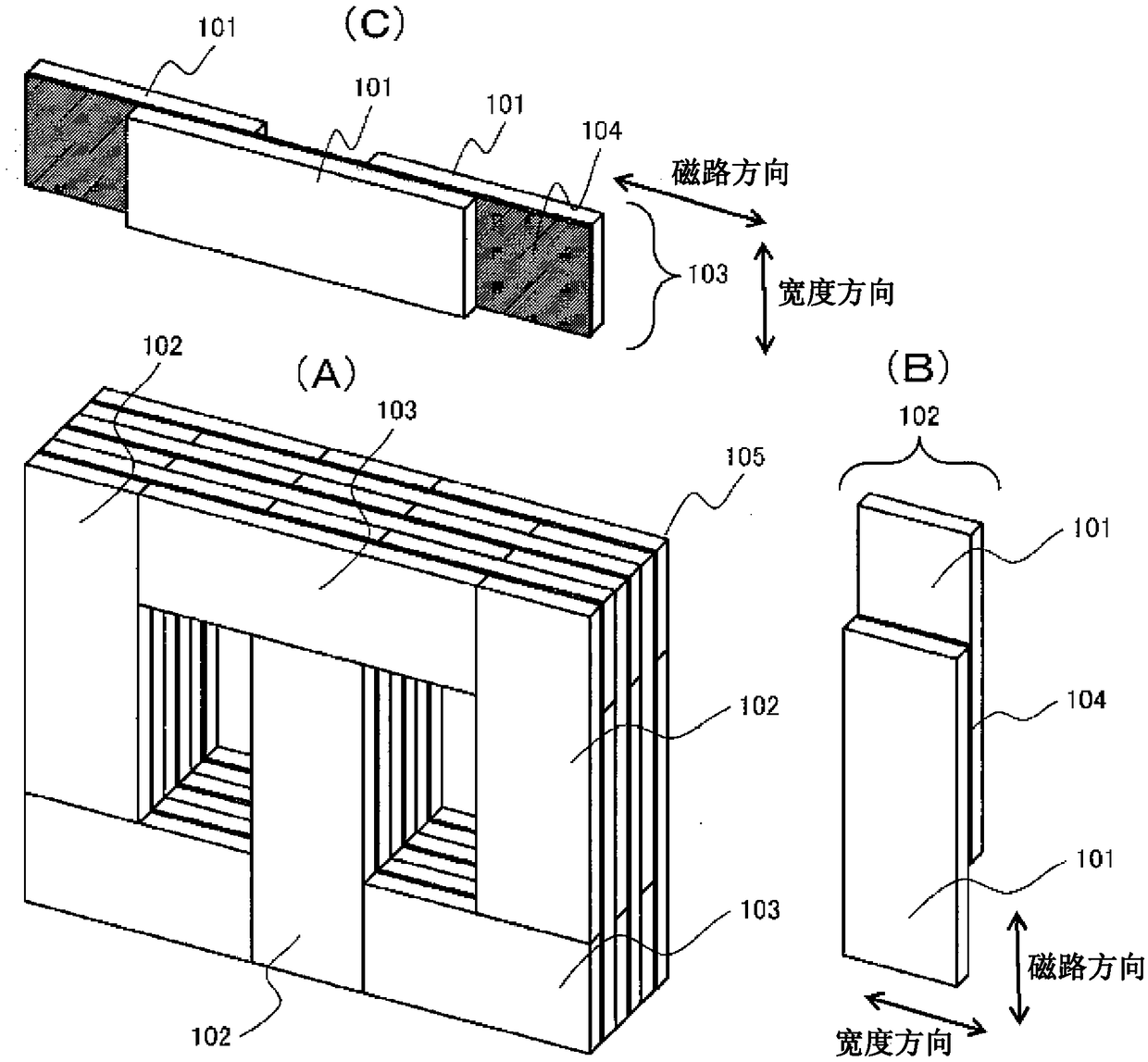
[0021] In this embodiment, a laminated body for an amorphous transformer is formed by sandwiching silicon steel sheets between two or more laminated bodies formed by laminating a plurality of amorphous alloy thin strips, and a laminated block bonded and fixed by a coating agent or the like. iron core. Use below figure 1 This embodiment will be described.
[0022] figure 1 This is a structural example of the three-leg amorphous laminated iron core of this embodiment. exist figure 1 Among them, (A) represents an amorphous laminated iron core 105, which is composed of a combination of a plurality of stem portion laminated blocks 102 and a yoke portion laminated block 103, and the stem portion laminated blocks 102 and magnetic The yoke laminated block 103 is a laminated block formed by sandwiching a silicon steel sheet 104 between a laminated body 101 obtained by laminating amorphous alloy thin strips as an amorphous material. (B) shows the stem portion laminated block 102 of...
Embodiment 2
[0034] In this embodiment, the adhesive fixing of the laminated block of the stem portion and the laminated block of the yoke portion and the additional conditions for the number of laminated sheets will be described.
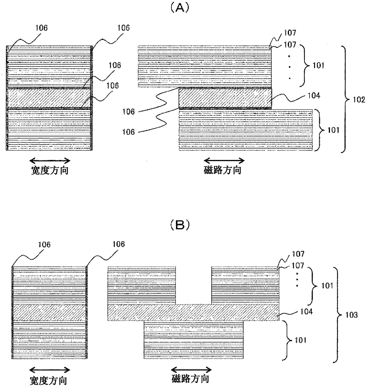
[0035] figure 2 It is a top view of the stem part laminated block and the yoke part laminated block of this embodiment. exist figure 2 Among them, (A) shows the structure of the stem portion laminated block 102 , and (B) shows the structure of the yoke portion laminated block 103 .
[0036] exist figure 2 In (A), the right side represents the direction of the magnetic circuit from the stacked block 102 of the stem portion (refer to figure 1 (B)) A plan view when viewed from the cross-sectional direction of the vertical laminated body 101, and the left side shows the width direction of the laminated block 102 from the stem part (refer to figure 1 (B)) Top view when viewed from the vertical direction.
[0037] Such as figure 2 As shown in (A), in the st...
Embodiment 3
[0045] In this embodiment, the shape of the joint end of the laminated body of the core column laminated block and the yoke laminated block and the silicon steel sheet will be described.
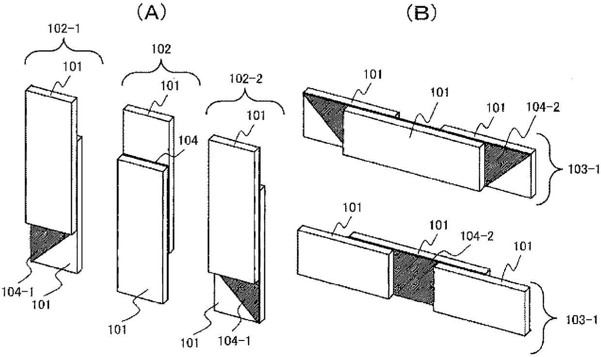
[0046] image 3 It is a perspective view of the stem part laminated block and the yoke part laminated block of the amorphous laminated iron core of this Example. image 3 Among them, (A) shows the structure of the laminated block of the stem part, and (B) shows the structure of the laminated block of the yoke part.
[0047] exist image 3 (A), with figure 1 (B) is different in that the shape of the joint end of the silicon steel sheet is different. That is, the laminated body 101 of the amorphous alloy thin strips 107 has a rectangular shape, and the silicon steel sheet has a frame shape 104-1 having a shape of 45 degrees.
[0048] Such as image 3 As shown in (A), there are three types of stem portion laminated blocks 102 102-1, 102, and 102-2, and 102-1 and 102-2 are stems of silicon ...
PUM
 Abstract
Description
Claims
Application Information
 - R&D
- Intellectual Property
- Life Sciences
- Materials
- Tech Scout
- Unparalleled Data Quality
- Higher Quality Content
- 60% Fewer Hallucinations
Browse by: Latest US Patents, China's latest patents, Technical Efficacy Thesaurus, Application Domain, Technology Topic, Popular Technical Reports.
© 2025 PatSnap. All rights reserved.Legal|Privacy policy|Modern Slavery Act Transparency Statement|Sitemap|About US| Contact US: help@patsnap.com