Service life control for energy stores

A technology of energy storage and controller, applied in battery/fuel cell control devices, instruments, current collectors, etc., can solve the problems of size, operating parameters, large cooling power, etc., and achieve the effects of prolonging life, avoiding aging, and simple power

Inactive Publication Date: 2018-10-23
SIEMENS AG
View PDF12 Cites 4 Cited by
  • Summary
  • Abstract
  • Description
  • Claims
  • Application Information

AI Technical Summary

Problems solved by technology

This tolerance buffer is associated with additional effort and costs or losses, such as excessive dimensions, limitations of operating parameters (eg maximum voltage) or greater installed cooling capacity

Method used


Image

  • Service life control for energy stores
  • Service life control for energy stores
  • Service life control for energy stores

Examples


Embodiment Construction

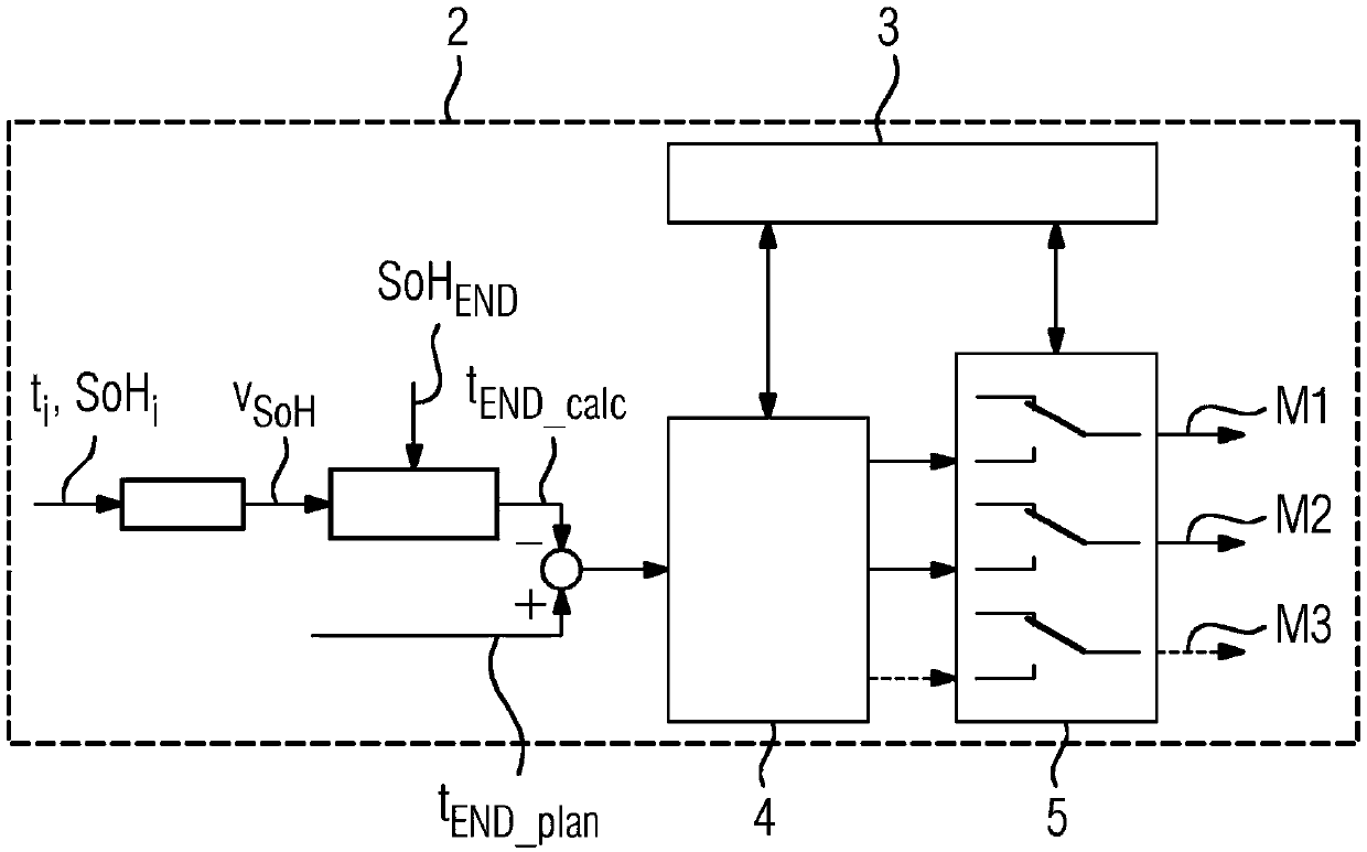
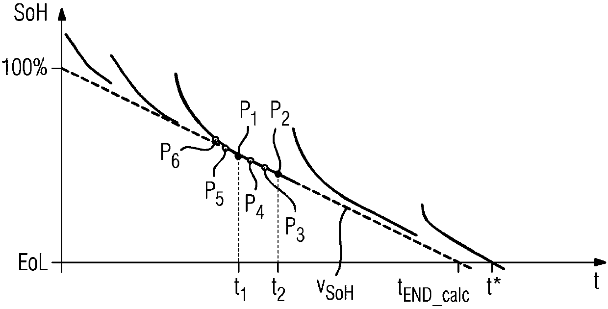
[0043] figure 1 A block diagram of a controller for influencing the lifetime of an energy storage module 1 (not shown here) is shown. Regarding the energy storage module 1 at different time points t i Aging state SoH 1 The signal of is used as the input parameter of the regulation system. Each aging state SoH i For example, it can be determined via the internal resistance or capacity of the energy storage module 1 . By Aging State SoH i At least two of them belong to the time point t i Capable of determining the aging rate v SoH . For example, the aging speed is obtained as follows, that is, using two aging states SoH i The difference is divided by the time point t to which it belongs i poor. Additional Aging States SoH i Can be used, for example, to improve the determination of the aging rate in terms of accuracy. In addition to going through two aging states SoH i The difference between to calculate the aging speed v SoH It also proves reasonable to determine t...


PUM


Abstract

The invention relates to a method for controlling the service life of an energy storage module (1), wherein a state of health (SoH) of the energy storage module (1) is known at different times (t). Inorder to improve the control of the service life of an energy storage module (1), it is proposed that a speed of ageing (vSoH) is determined from a first known state of health (SoH1), in which the energy storage module (1) is at a first time (t1), and a second state of health (SoH2), in which the energy storage module (1) is at a second time (t2), wherein a time (tEND_calc) of a determined end ofservice life is calculated from the speed of ageing (vSoH) and from one of the states of health (SoH), wherein depending on the time (tEND_calc) of the determined end of service life a measure for changing the service life of the energy storage module (1) is applied.

Description

technical field [0001] The invention relates to a method for controlling the lifetime of an energy storage module, wherein the state of aging of the energy storage module is known at different points in time. The invention also relates to a method for controlling the lifetime of a plurality of energy storage modules. Furthermore, the invention relates to a controller for an energy storage module as well as an energy storage module and an energy storage system with such a controller. Furthermore, the invention relates to a vehicle with such an energy storage module. Background technique [0002] Energy storage can be constructed from one or more energy storage modules. In this case, the energy storage module usually includes a sensor for determining the temperature of the energy storage module. Furthermore, the energy storage modules are usually assigned a regulating or control unit with which the performance and operation of the energy storage modules can be influenced. ...

Claims


Application Information

Patent Timeline
Patent Type & Authority Applications(China)
IPC IPC(8): H01M10/42B60L3/12B60L11/18G01R31/36H01M10/48H02J7/00
CPCB60L3/12H01M10/42H01M10/4207H01M10/48H01M10/482H01M2220/20G01R31/392B60L58/16B60L58/24H02J7/0069Y02T10/70Y02E60/10B60L58/13Y02E60/13G01R31/367G01R31/396H01M10/486B60L58/26B60W20/20
Inventor 斯文·鲁珀特欧根·霍尔
Owner SIEMENS AG
Why Eureka
Try Eureka