PON-CAN bus architecture and robot system

A PON-CAN and robot system technology, applied in the field of communication control, can solve the problems of limited number of connected nodes and low CAN bus transmission rate, achieve high bandwidth, solve the problem of low communication rate, and improve the stability of electromagnetic compatibility

Active Publication Date: 2018-10-23
CLOUDMINDS SHANGHAI ROBOTICS CO LTD
View PDF5 Cites 5 Cited by
  • Summary
  • Abstract
  • Description
  • Claims
  • Application Information

AI Technical Summary

Problems solved by technology

[0004] The main purpose of this disclosure is to provide a PON-CAN bus architecture and robot system to solve the problems of low transmission rate and limited number of connected nodes in the existing CAN bus

Method used


Image

  • PON-CAN bus architecture and robot system
  • PON-CAN bus architecture and robot system
  • PON-CAN bus architecture and robot system

Examples


Embodiment Construction

[0025] In order to make the purpose, technical solutions and advantages of the embodiments of the present disclosure clearer, the technical solutions in the embodiments of the present disclosure will be clearly and completely described below in conjunction with the drawings in the embodiments of the present disclosure. Obviously, the described embodiments It is a part of embodiments of the present invention, but not all embodiments. Based on the embodiments of the present invention, all other embodiments obtained by persons of ordinary skill in the art without creative efforts fall within the protection scope of the present invention.

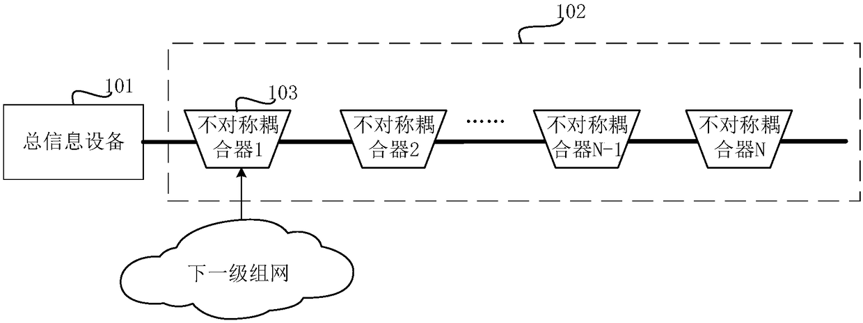
[0026] Embodiments of the present disclosure provide a PON-CAN bus architecture, such as figure 1 As shown, the PON-CAN bus architecture includes a general information device 101 and a fiber optic bus connected to the general information device 101, wherein the fiber optic bus is formed by interconnecting a plurality of asymmetric couplers. E....


PUM


Abstract

A PON-CAN bus architecture and a robot system, the PON-CAN bus architecture comprising an optical fiber bus and a total information device connected to the optical fiber bus, the optical fiber bus being formed by interconnecting a plurality of asymmetric couplers; the symmetric couplers are configured to branch the next level network; the total information device is configured to perform communication interaction with the next level network through the optical fiber bus. The robotic system includes the PON-CAN bus architecture, and various terminal control systems and terminal sensing devicesof robots connected to the PON-CAN bus architecture.

Description

technical field [0001] The present disclosure relates to the field of communication control, in particular to a PON-CAN bus architecture and a robot system. Background technique [0002] CAN is the abbreviation of Controller Area Network. The characteristic of CAN bus is that there is no master-slave distinction in data communication. Any node can initiate data communication to any other (one or more) nodes without being affected by a single node. Node damage leads to bus paralysis effects. However, in the related art, the maximum transmission rate of the CAN bus is 1 Mbps, and as the distance between two nodes increases, the communication rate of the CAN bus will slow down, so that the number of nodes connected to the CAN bus is limited. [0003] With the development of science and technology, the scope of application of control systems continues to expand, and more and more nodes are controlled, such as robot systems, which have the characteristics of large amounts of mov...

Claims


Application Information

Patent Timeline
Patent Type & Authority Applications(China)
IPC IPC(8): H04Q11/00H04L12/40
CPCH04L12/40006H04L2012/40215H04Q11/0067H04Q2011/009
Inventor 黄晓庆朱显忠
Owner CLOUDMINDS SHANGHAI ROBOTICS CO LTD
Why Eureka
Try Eureka