A force-amplified driving device based on shape memory alloy

A technology of memory alloy and driving device, which is applied in the direction of machines/engines, mechanisms for generating mechanical power, mechanical equipment, etc. It can solve the problems of limited application range, complex structure of force driving device, and large resistance, so as to save locking and unlocking Mechanism, mass reduction, overall weight reduction effect

Inactive Publication Date: 2019-09-13
HARBIN INST OF TECH
View PDF5 Cites 0 Cited by
  • Summary
  • Abstract
  • Description
  • Claims
  • Application Information

AI Technical Summary

Problems solved by technology

[0004] In order to solve the problems of complex structure, excessive resistance and too limited application range of the existing force drive device of the aircraft, the present invention further proposes a force amplification drive device based on a shape memory alloy

Method used


Image

  • A force-amplified driving device based on shape memory alloy
  • A force-amplified driving device based on shape memory alloy
  • A force-amplified driving device based on shape memory alloy

Examples


specific Embodiment approach 1

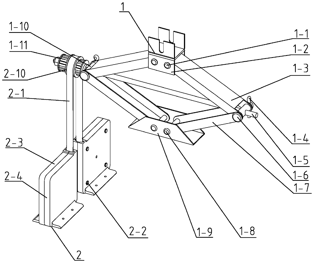
[0020] Specific implementation mode one: combine Figure 1 to Figure 7 Describe this embodiment, a force amplification drive device based on a shape memory alloy described in this embodiment includes a force amplification mechanism 1 and a shape memory alloy drive mechanism 2, and the force amplification mechanism 1 includes a top bracket 1-2, a screw 1-5, Threaded hole pin 1-6, base 1-9, light hole pin 1-10, spline shaft 1-11, two upper support arms 1-3 and two lower support arms 1-7, two lower supports The arms 1-7 are relatively arranged, the lower end of the lower support arm 1-7 is rotationally connected with the base 1-9, and the upper end of a lower support arm 1-7 is connected to the lower end of an upper support arm 1-3 through the light hole pin shaft 1-10 Hinged, the upper end of another lower support arm 1-7 is hinged with the lower end of another upper support arm 1-3 through threaded hole pin shaft 1-6, two upper support arms 1-3 are arranged oppositely, and uppe...

specific Embodiment approach 2

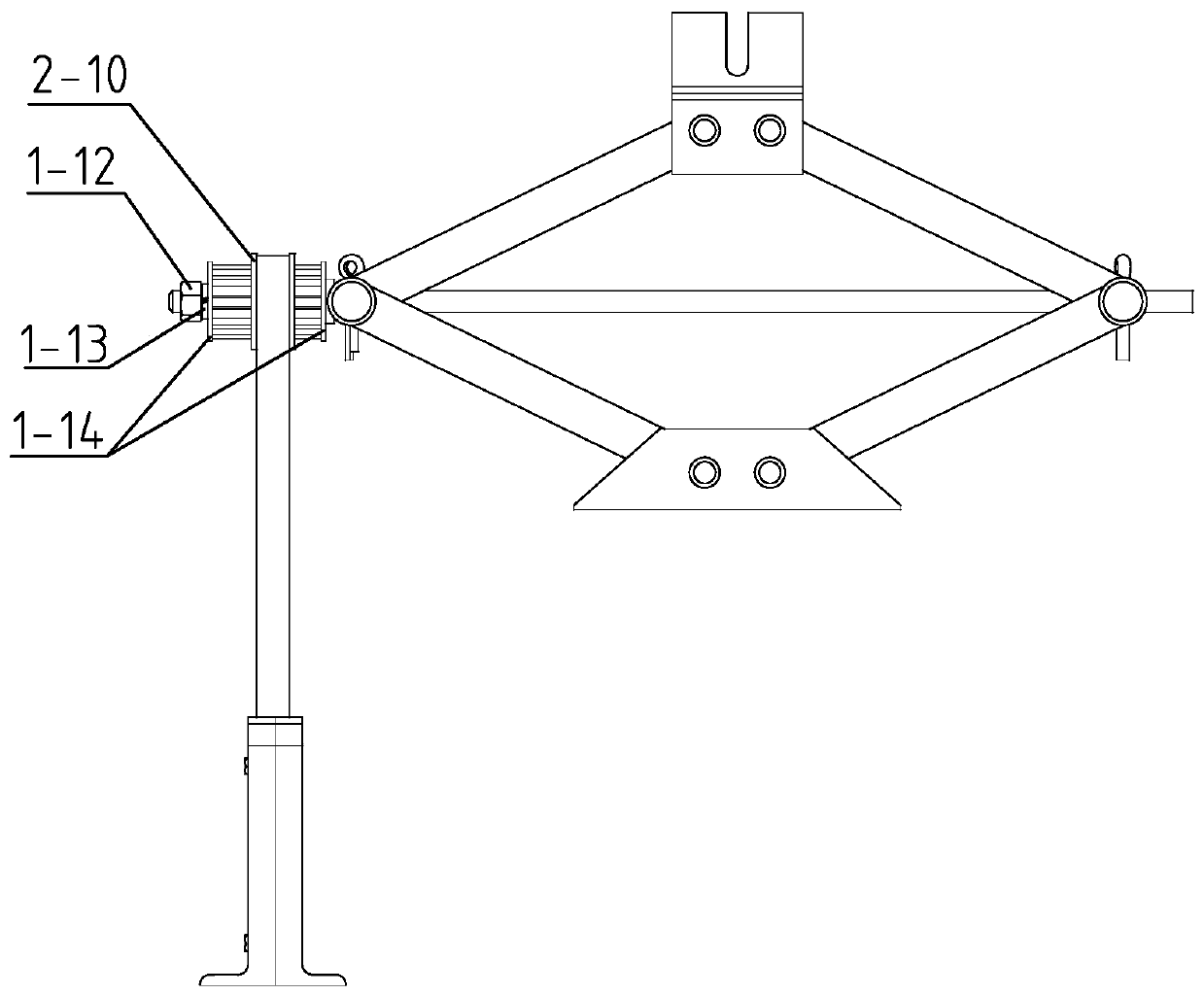
[0026] Specific implementation mode two: combination Figure 1 to Figure 2To illustrate this embodiment, one end of the screw 1-5 in this embodiment is provided with a shoulder, and the shoulder is caught on the outer peripheral side wall of the light hole pin 1-10. Other compositions and connection methods are the same as those in Embodiment 1.

[0027] One end of the screw rod 1-5 is designed in this way to be positioned by the shoulder of the screw rod 1-5, so that the relative position of the screw rod 1-5 and the pin shaft 1-10 of the light hole remains unchanged.

specific Embodiment approach 3

[0028] Specific implementation mode three: combination Figure 1 to Figure 4 To illustrate this embodiment, a thrust washer 1-14 is respectively provided on both ends of the spline shaft 1-11 in this embodiment, and the thrust washer 1-14 is set on the screw rod 1-5, and the spline shaft 1 The outside of the thrust washer 1-14 at the -11 outer side is provided with a nut 1-12, and the nut 1-12 is screwed on the end of one end of the screw rod 1-5, and the nut 1-12 is connected with the thrust washer at the outer side of the spline shaft 1-11 Spring washers 1-13 are provided between 1-14. Other compositions and connection methods are the same as those in the second embodiment.

[0029] In such a design, the splined shaft 1-11 and the light hole pin shaft 1-10 on one end of the screw rod 1-5 are effectively positioned.


PUM


Abstract

The invention discloses a force magnification driving device based on shape memory alloy, and relates to the technical field of deformable aircrafts. In order to solve the problems that a force driving device of an existing aircraft is complicated in structure, excessively large in resistance and excessively limited in application range, the force magnification driving device comprises a force magnification mechanism and a shape memory alloy driving mechanism. The force magnification mechanism comprises a top support, a screw rod, a threaded hole pin shaft, a pedestal, an unthreaded hole pin shaft, a spline shaft, two upper supporting arms and two lower supporting arms. The shape memory alloy driving mechanism comprises a flat belt, an outer belt wheel and two driving units. Each driving unit comprises an outer shell, a shape memory alloy belt and an inner belt wheel. The force magnification driving device based on the shape memory alloy can be used in the deformable aircrafts.

Description

technical field [0001] The invention relates to the technical field of deformable aircraft, in particular to a force amplification drive device based on a shape memory alloy. Background technique [0002] In the field of aerospace, deformable aircraft is of great significance to the development of aircraft. In the design process of deformable aircraft, in order to improve the endurance time of the aircraft and reduce its manufacturing cost, the mass of the aircraft deformation drive device needs to be reduced as much as possible. However, the traditional aircraft deformation drive device has a large mass and cannot well meet the aerospace requirements. In addition, the aircraft may be interfered by the channel, the external environment and the enemy in actual work, so the anti-electromagnetic interference capability plays a very important role in the selection of the aircraft deformation drive device, while the traditional motor drive device is easily affected by the above f...

Claims


Application Information

Patent Timeline
Patent Type & Authority Patents(China)
IPC IPC(8): F03G7/06
Inventor 李柠汐张荣茹张征徐晓涵张继元
Owner HARBIN INST OF TECH
Why Eureka
Try Eureka