
Robot rotating base

A technology of robots and reducers, applied in the field of robots, can solve the problems of poor load-bearing capacity, short service life of cables, and poor rigidity of the swivel structure, and achieve the effects of clear cable arrangement, improved stability and reasonable design.

Pending Publication Date: 2018-10-26
广西宏太智能机器人制造有限公司
View PDF0 Cites 1 Cited by
  • Summary
  • Abstract
  • Description
  • Claims
  • Application Information

AI Technical Summary

Problems solved by technology

[0002] Due to the relatively complex structure of the robot, the existing robot swivel structure is basically integral, which makes processing difficult, the structural design is difficult to arrange reasonably, the motor layout is unreasonable, and its own structure is relatively heavy; the swivel structure has poor rigidity and poor load-bearing capacity. ; The wiring is unscientific, and the service life of the cable is short

Method used


Image

  • Robot rotating base
  • Robot rotating base
  • Robot rotating base

Examples


Embodiment Construction

[0015] The specific implementation of the present invention will be further described below in conjunction with the accompanying drawings.

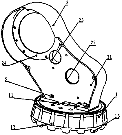
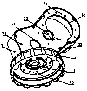
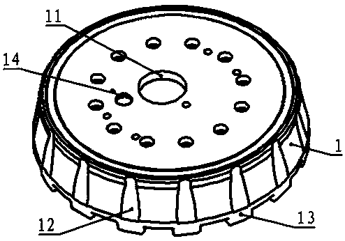
[0016] As shown in the figure, a robot swivel seat, the first shaft part 1 and the second shaft part 2 are fixedly connected by bolts 3; the upper end of the first shaft part 1 is provided with a first reducer output end The flange 15 and the threading hole 11 are located in the middle of the first shaft part 1; the second motor mounting hole 21 and the second motor shaft avoidance hole 22 are provided on the lower half of the second shaft part 2; the upper half The second reducer mounting flange 24 and the threading hole III 26 are provided at the top; the threading hole II 23 is located in the middle of the second shaft part 2; by machining the first shaft part 1 and the second shaft part 2 respectively, then Assembled and combined together, this greatly reduces the difficulty of machining, and the cables are introduced from the hollow ...


PUM


Abstract

The invention discloses a robot rotating base. A first shaft part and a second shaft part are fixedly connected through a bolt, a first speed reducer output end mounting flange is arranged on the upper end face of the first shaft part, a wire penetrating hole is formed in the middle of the first shaft part, a second motor mounting hole and a second motor shaft avoiding hole are formed in the lowerhalf part of the second shaft part, a second speed reducer mounting flange and a wire penetrating hole III are formed on the upper half part, a wire penetrating hole II is located in the middle of the second shaft part, the first shaft part and the second shaft part are machined and then are assembled and combined together, the machining difficulty is greatly reduced, a cable is guided in from ahollow first speed reducer, passes through the wire penetrating hole I, then passes through the wire penetrating hole II, and is guided out of the wire penetrating hole III, cable arranging is clear,design is reasonable, a second motor is arranged on the lower half part of the second shaft part, the gravity center of the rotating base is reduced, and the whole stability of the robot is improved.

Description

technical field [0001] The invention relates to the technical field of robots, in particular to a robot transfer seat. Background technique [0002] Due to the relatively complex structure of the robot, the existing robot swivel structure is basically integral, which makes processing difficult, the structural design is difficult to arrange reasonably, the motor layout is unreasonable, and its own structure is relatively heavy; the swivel structure has poor rigidity and poor load-bearing capacity. ; The wiring is unscientific, and the service life of the cable is short. Contents of the invention [0003] The purpose of the present invention is to provide a robot swivel seat, which has the advantages of simple structure, reasonable layout, clear cable arrangement channel, lower center of gravity, increased stability of the robot as a whole, and easy processing of split type. [0004] The technical solution adopted in the present invention is: a robot turntable, the first sh...

Claims


Application Information

Patent Timeline
IPC IPC(8): B25J19/00
CPCB25J19/00
Inventor 许海军庞桂福杨镇锋
Owner 广西宏太智能机器人制造有限公司
Learn More