Built-in metal vibrator vibration and noise reduction dynamic vibration absorber structure of steel rail

A dynamic vibration absorber, vibration reduction and noise reduction technology, applied in tracks, roads, buildings, etc., can solve problems such as falling off, loose installation, and shift of the center of gravity of the overall structure, so as to increase bearing, reduce vertical vibration, and reduce lateral vibration. The effect of vibration

Active Publication Date: 2018-10-26
SHANGHAI UNIV OF ENG SCI
View PDF7 Cites 14 Cited by
  • Summary
  • Abstract
  • Description
  • Claims
  • Application Information

AI Technical Summary

Problems solved by technology

[0004] The rail shock absorber whose patent application number is 200480009892.6 has the following two disadvantages: one is that the resonant material only adopts one kind of elastic material, which can only suppress one or a small range of frequencies during use; The vibration damping device is only installed at the lower end of the rail, without considering the entire rail waist, and cannot achieve the best vibration damping effect
[0005] The constrained damping vibration and noise reduction plate with the patent application number 201621424869.X has the following two disadvantages: First, the part of the material where the vibration and noise reduction plate is bonded to the rail does not have damping characteristics, and it is easy to be damaged during the vibration reduction process. Cause se

Method used


Image

  • Built-in metal vibrator vibration and noise reduction dynamic vibration absorber structure of steel rail
  • Built-in metal vibrator vibration and noise reduction dynamic vibration absorber structure of steel rail
  • Built-in metal vibrator vibration and noise reduction dynamic vibration absorber structure of steel rail

Examples


Embodiment Construction

[0051] The present invention will be further described below in conjunction with accompanying drawing.

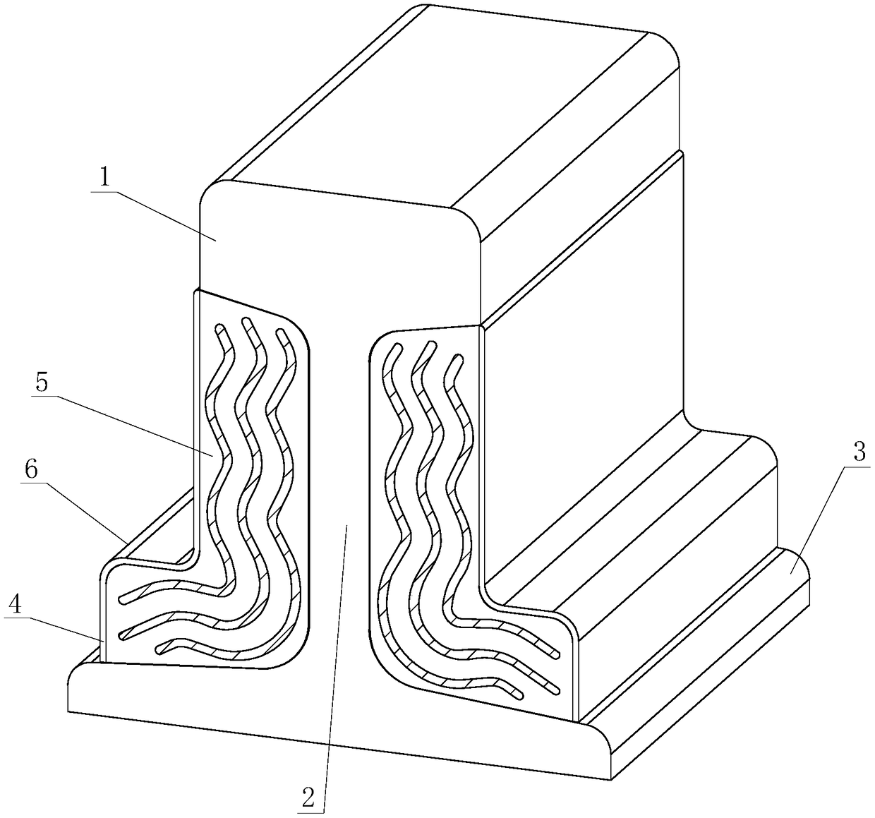
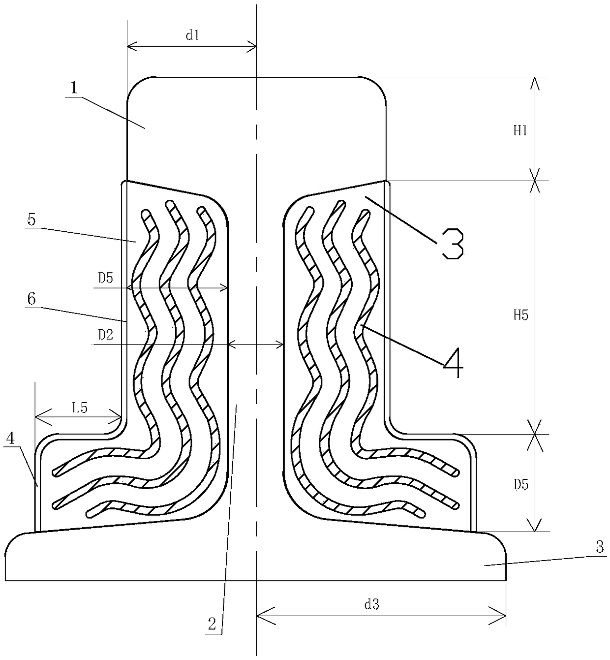
[0052] Such as figure 1 , Figure 4 The built-in metal vibrator vibration and noise reduction dynamic vibration absorber structure of the rail shown is arranged on both sides of the rail waist 2 between two adjacent fasteners, including the inclusion protection layer 4, the elastic damping body 5 and the metal mass body 6.

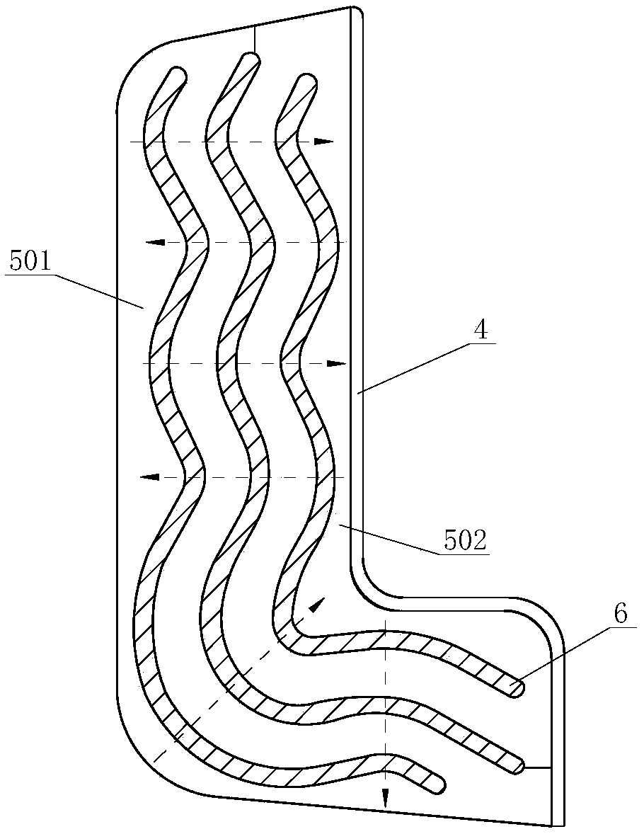
[0053] The metal mass body 6 is a plurality of meandering wavy metal plates, which are nested in the elastic damping body 5 at intervals, and a metal material with a relatively high density is selected as the vibrator of the rail vibration absorber. On the premise of satisfying the sufficient strength of the elastic damping body 5 , using the curved surface to increase the effective working area of ​​damping and improve the vibration transmission attenuation rate.

[0054] The elastic damping body 5 is appropriately selected from a material with rela...


PUM


Abstract

The invention provides a built-in metal vibrator vibration and noise reduction dynamic vibration absorber structure of a steel rail. The structure is arranged on the two sides of a steel rail web between two adjacent fasteners and comprises coating body protecting layers, elastic damping bodies and metal mass bodies. Each elastic damping body is tightly attached and fixed to the steel rail and comprises a first elastic damping body and a second elastic damping body which are stacked and fixed into a whole, wherein the hardness of each first elastic damping body is larger than that of each second elastic damping body. Each metal mass body is made of multiple wriggling wavy metal plates which are nested in the corresponding elastic damping body at intervals. Each coating body protecting layer covers the exposed face of the corresponding elastic damping body. By the adoption of the structure, on the premise that the requirement for the sufficient strength of a damping material is met, thedamping effective working area is increased in a wriggling mode, the vibration transmission attenuation rate is increased, the damping material has two different degrees of hardness so as to meet thevibration reduction requirements in different frequency ranges, rail traffic operation noise can be effectively reduced from the position of a noise source, and utilization of the structure does notaffect maintenance of rail traffic original infrastructures and rails.

Description

technical field [0001] The invention relates to the field of rail transit vibration reduction and noise reduction, in particular to a built-in metal vibrator vibration reduction and noise reduction device. Background technique [0002] Railways are considered an environmentally friendly means of transportation, providing a clean and efficient means of transportation. However, the noise caused by railway operation has become a source of sound pollution that cannot be ignored in the area along the track, causing considerable trouble to the work and life of residents along the line. At the same time, the noise problem is also one of the main factors limiting the speed and passenger capacity of rail vehicles. The main noise in rail traffic is caused by the wheel-rail rolling contact, the roughness on the wheel and the track forms an excitation and causes the wheel-rail to vibrate. The structure radiates noise as vibrations travel through the wheels and tracks. In order to red...

Claims


Application Information

Patent Timeline
IPC IPC(8): E01B19/00
CPCE01B19/003
Inventor 文永蓬邹钰纪忠辉祁慧孙倩尹波润郭林生宗志祥郑晓明
Owner SHANGHAI UNIV OF ENG SCI
Why Eureka
Try Eureka