Pile head breaking and cutting device for bridge cast-in-place pile and using method

A cast-in-place pile and pile head technology, applied in sheet pile wall, construction, infrastructure engineering and other directions, can solve the problems of difficulty in removal, high cost and high structural strength, and achieve the goal of reducing cost, reducing concrete thickness and improving construction efficiency. Effect

Active Publication Date: 2018-10-26
JIANGSU PROVINGIAL TRANSPORTATION ENG GRP
View PDF5 Cites 4 Cited by
  • Summary
  • Abstract
  • Description
  • Claims
  • Application Information

AI Technical Summary

Problems solved by technology

[0004] However, when using this hydraulic pile breaker to remove the pile heads one by one, because the cast-in-place piles have been completely solidified, the structural strength is high, the removal is difficult, and the cost is high.

Method used


Image

  • Pile head breaking and cutting device for bridge cast-in-place pile and using method
  • Pile head breaking and cutting device for bridge cast-in-place pile and using method
  • Pile head breaking and cutting device for bridge cast-in-place pile and using method

Examples


Embodiment 1

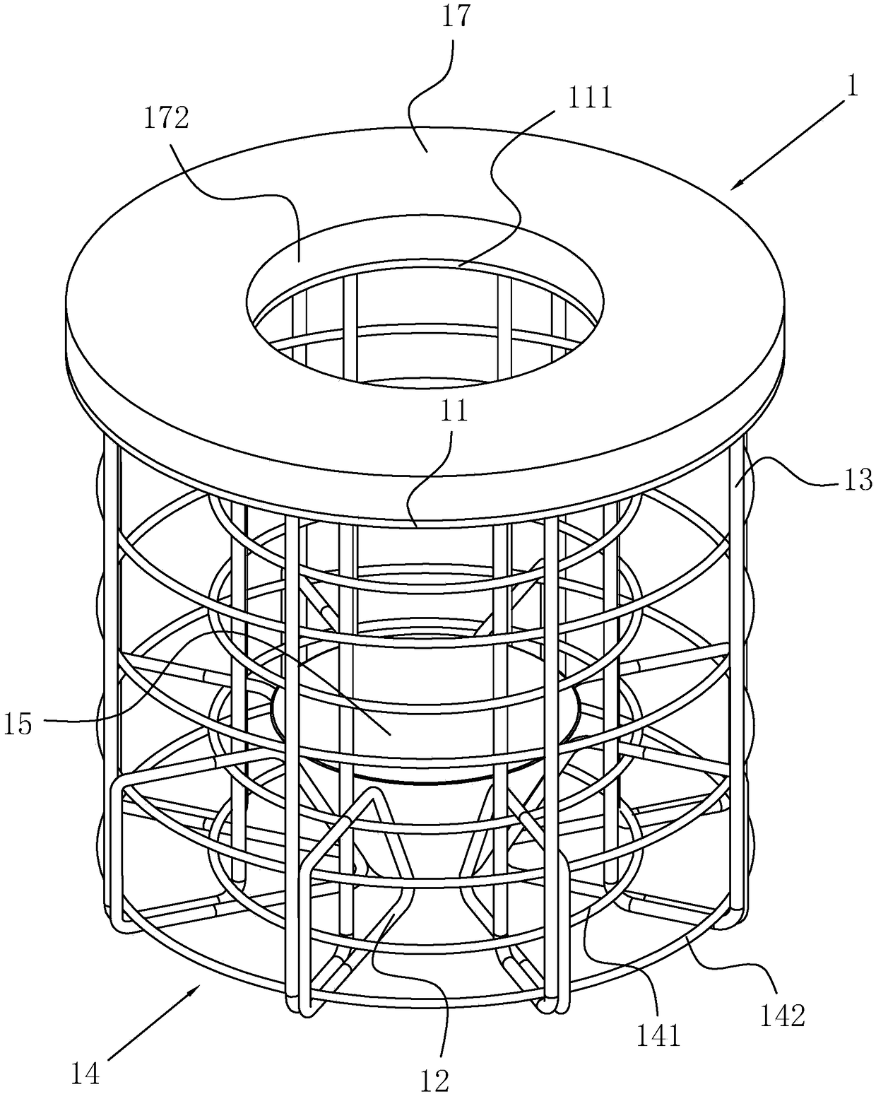
[0043] A pile head breaking and shearing device for cast-in-situ bridge piles, such as figure 1As shown, the shearer body 1 is included. Here, the size of the shearer body 1 is determined according to the diameter of the cast-in-situ pile and the designed pile head length, and the shearer body 1 includes a cover plate 11 arranged in a disc shape. 11 has a relief hole 111 in the center, and a plurality of vertically arranged crushing ribs 12 are arranged at intervals around the axis of the cover plate 11 at the bottom of the cover plate 11. Here, the crushing ribs 12 are arranged in a frame structure.

[0044] Generally, the actual pouring length of the cast-in-place pile is greater than the calculated length setting, so that the sediment at the bottom of the pile and the impurities precipitated in the mud during the pouring process gradually gather to the top of the cast-in-place pile to form a certain thickness of laitance, so that after the pile head is removed, the cast-in-s...

Embodiment 2

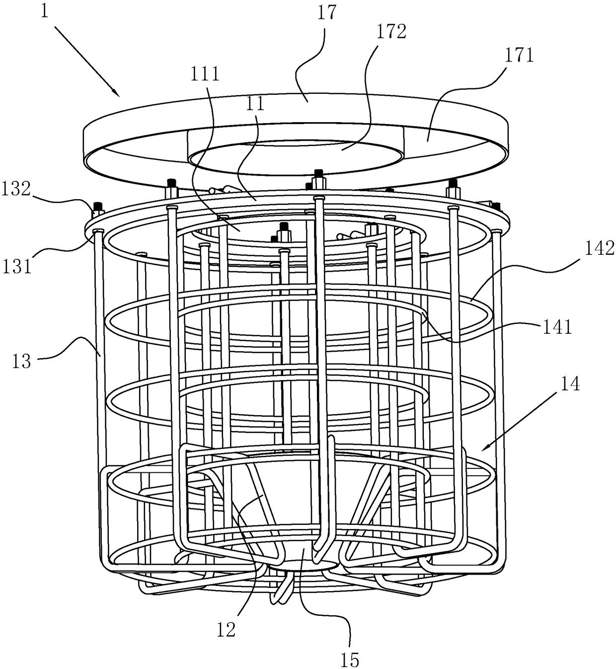
[0061] This embodiment is substantially the same as Embodiment 1, the difference is that in order to further stabilize the structure of the shearer body 1, as figure 2 As shown, the broken tendons 12 are sleeved on two groups of reinforcing hoops 14 at the bottom of the high-strength U-shaped bolts 13, and the radius of the first reinforcing hoop 141 is equal to the radius of the cylinder surrounded by a plurality of high-strength U-shaped bolts 13. The second reinforced The radius of the hoop 142 is equal to the radius of the cylinder surrounded by a plurality of high-strength U-shaped bolts 13 outside. In this way, on the one hand, the forced deformation of the first reinforcement hoop 141 and the second reinforcement hoop 142 and the high-strength U-shaped bolt 13 is used to realize the socket connection of the reinforcement hoop group 14; Outside the two sets of reinforcing hoops 14 at the bottom of the body 1, the reinforcing hoops 14 are used to locate the position of t...


PUM


Abstract

The invention provides a pile head breaking and cutting device for a bridge cast-in-place pile, and relates to the field of cast-in-place piles. The device comprises a breaking and cutting device body, wherein the breaking and cutting device body comprises a cover plate which is arranged in a disc shape, a plurality of vertically-arranged breaking ribs are arranged at the bottom end of the cover plate around the axis of the cover plate at intervals, and the breaking ribs are arranged in a frame structure. The invention further provides a using method of the pile head breaking and cutting device for the bridge cast-in-place pile. The using method comprises the following steps that S1, the breaking and cutting device body is coaxially placed at the top end of a reinforcement cage; S2, the cast-in-place pile is cast by adopting a tremie method; S3, when concrete is initially set, a protecting cover is taken off, and a lifting device is used for pulling lifting ribs to enable the whole breaking and cutting device body to be pulled away from the cast-in-place pile; and S4, when the concrete is finally set, a pile head is broken from an initial position of the breaking and cutting devicebody. The device and the method aim to solve the problems that in the prior art, the pipe head of the cast-in-place pile is difficult to break, and the cost is relatively high. According to the device and the method, the breaking and cutting device body arranged at the top of the reinforcement cage is taken out when the concrete is initially set, so that the strength of the pile head is reduced,the construction personnel can conveniently break down the pile head, and the cost is reduced.

Description

technical field [0001] The invention relates to the field of cast-in-place piles, in particular to a pile head breaking and shearing device for bridge cast-in-place piles and a method for using it. Background technique [0002] In pile foundation construction, in order to ensure the quality of the pile head, the general pile length should be set higher than the pile top elevation; when pouring cast-in-situ piles, the sediment at the bottom of the pile and the impurities precipitated in the mud during the pouring process will form a certain thickness on the concrete surface. Therefore, after the concrete is solidified, the overfilling part will be chiseled off, the main reinforcement above the pile top level will be exposed, and the pile cap will be constructed after passing the pile foundation inspection. [0003] And in order to chisel out the super-filling part, at present, the Chinese utility model patent with the notification number CN203514317U discloses a hydraulic pil...

Claims


Application Information

Patent Timeline
Patent Type & Authority Applications(China)
IPC IPC(8): E02D9/00E02D5/34
CPCE02D5/34E02D9/00
Inventor 巫亚明束瑞
Owner JIANGSU PROVINGIAL TRANSPORTATION ENG GRP
Why Eureka
Try Eureka