Steel keel building wall and foundation heat insulation bridge structure and construction method

A technology for building walls and steel keels, which is applied to building components, building structures, and thermal insulation. It can solve problems such as heat loss, complex structures, difficult to consider design requirements for structures, waterproofing, and heat-breaking bridges, etc., to avoid heat loss. The loss, the effect of solving the thermal break bridge

Pending Publication Date: 2018-10-26
SHENYANG JIANZHU UNIVERSITY
View PDF0 Cites 0 Cited by
  • Summary
  • Abstract
  • Description
  • Claims
  • Application Information

AI Technical Summary

Problems solved by technology

[0003] Taking the steel keel building wall as an example, the foot of the wall is at the contact position between the building wall and the ground, and it is the node where multiple components such as the building wall, building foundation wall / beam, and indoor ground meet. It is difficult to consider the balance of design requirements such as structure, waterproof, and heat-breaking bridges
[0004] Usually, the building wall and indoor floor are directly connected to the building foundation wall / beam, and the indoor heat will be transferred from the building foundation wall / beam to the ground through the building wall and indoor floor, resulting in heat loss

Method used


Image

  • Steel keel building wall and foundation heat insulation bridge structure and construction method
  • Steel keel building wall and foundation heat insulation bridge structure and construction method
  • Steel keel building wall and foundation heat insulation bridge structure and construction method

Examples


Embodiment Construction

[0034] The present invention will be further described in detail below in conjunction with the accompanying drawings and specific embodiments.

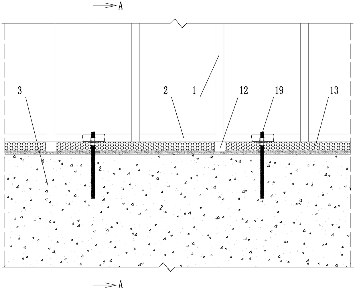
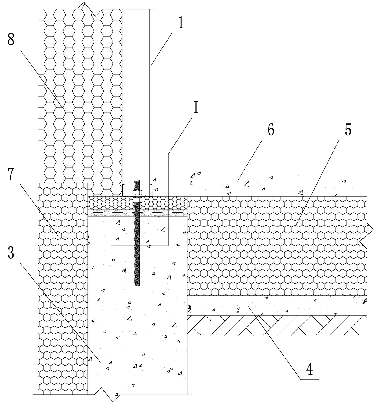
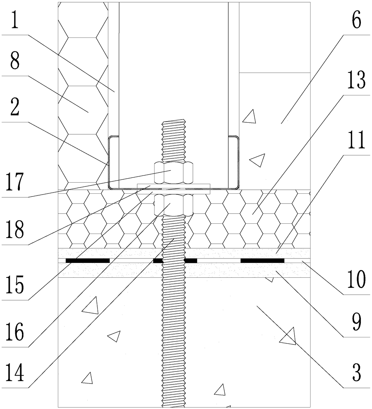
[0035] Such as Figure 1~3 As shown, a thermal insulation bridge structure at the foot of the wall of a steel keel building, including wall steel columns 1, wall steel keel bottom beams 2, foundation walls / beams 3, indoor ground concrete cushion 4, and indoor ground insulation layer 5 , Indoor ground concrete structure layer 6, foundation wall / beam insulation layer 7, wall insulation layer 8, leveling layer 9, moisture-proof / water layer 10, adhesive slurry layer 11, heat-breaking bridge support block 12, heat-breaking bridge insulation The plate 13 and the thermal break bridge bolt connection assembly 19; the wall steel column 1 is fixed on the wall steel keel bottom beam 2, and the wall steel keel bottom beam 2 is connected to the foundation wall / beam through the heat break bridge bolt connection assembly 19 3. The tops are fixedly ...


PUM


Abstract

The invention discloses a steel keel building wall and foundation heat insulation bridge structure and a construction method. The heat insulation bridge structure comprises wall steel vertical columns, a wall steel keel bottom beam, a base wall / beam, an indoor ground concrete cushion, an indoor ground heat insulation layer, an indoor ground concrete structure layer, a base wall / beam heat insulation layer, a wall heat insulation layer, a leveling layer, a moisture / water-resistant layer, a bonding slurry layer, heat insulation bridge supporting blocks, a heat insulation bridge heat preservationplate and a heat insulation bridge bolt connecting component. The heat insulation bridge bolt connecting component comprises a heat insulation bridge screw, a bottom supporting plate, a leveling nut,a tightening nut and a tightening spacer. The construction method includes the steps: preparing the leveling layer and the moisture / water-resistant layer at the top end of the base wall / beam, and screwing the leveling nut and the bottom supporting plate in the heat insulation bridge screw; coating the upper surface of the moisture / water-resistant layer with the bonding slurry layer, and mounting the heat insulation bridge heat preservation plate and the heat insulation bridge supporting blocks; hoisting a steel keel building wall onto the base wall / beam, and fixedly connecting the steel keel building wall with the base wall / beam; laying the indoor ground heat insulation layer and the indoor ground concrete structure layer; mounting the wall and the base wall / beam heat insulation layer.

Description

technical field [0001] The invention belongs to the technical field of construction engineering, and in particular relates to a structure and a construction method of a thermal break bridge at the foot of a steel keel building wall. Background technique [0002] Building thermal bridges refer to reinforced concrete or metal beams / columns / ribs / fittings and other parts in the enclosure structures such as exterior walls and roofs. Due to the strong heat transfer capacity of these parts, the heat flow is relatively dense, and the inner surface temperature is relatively low. called a thermal bridge. [0003] Taking the steel keel building wall as an example, the foot of the wall is at the contact position between the building wall and the ground, and is the node where multiple components such as the building wall, building foundation wall / beam, and indoor ground meet. It is difficult to consider the balance of design requirements such as structure, waterproof, and heat-breaking ...

Claims


Application Information

Patent Timeline
IPC IPC(8): E04B1/76
CPCE04B1/76E04B2001/7679
Inventor 夏晓东郭喜峰李宏伟石羽周鹏
Owner SHENYANG JIANZHU UNIVERSITY
Why Eureka
Try Eureka