Garment cloth drying device

A technology for drying fabrics and clothing, applied in the field of clothing processing, can solve the problems of slow drying speed, low drying efficiency, waste of energy, etc., and achieve the effects of fast drying speed, improving drying efficiency and thorough drying.

Inactive Publication Date: 2018-10-26
柳晓燕
View PDF3 Cites 5 Cited by
  • Summary
  • Abstract
  • Description
  • Claims
  • Application Information

AI Technical Summary

Problems solved by technology

[0002] In the process of garment processing and production, the fabrics used in garment processing need to be cleaned, printed and dyed, dried and other processes. Drying the fabrics is an indispensable process in the production of fabrics. The existing drying devices mainly include square ovens. The electric heater in the oven, the cloth passes through the oven, and the heat generated by the electric heater is used to heat and dry the cloth. With this structure, due to the use of a square oven, the area to be heated in the oven is large, and the electric heating needs to be increased. the power of the dryer, but it wastes energy; at the same time, when the fabric has too much moisture, the drying speed of the oven is too slow, and the drying efficiency is low. At the same time, the drying temperature is too high and the fabric will be damaged.

Method used


Image

  • Garment cloth drying device
  • Garment cloth drying device
  • Garment cloth drying device

Examples


Embodiment Construction

[0017] The following will clearly and completely describe the technical solutions in the embodiments of the present invention with reference to the accompanying drawings in the embodiments of the present invention. Obviously, the described embodiments are only some, not all, embodiments of the present invention. Based on the embodiments of the present invention, all other embodiments obtained by persons of ordinary skill in the art without making creative efforts belong to the protection scope of the present invention.

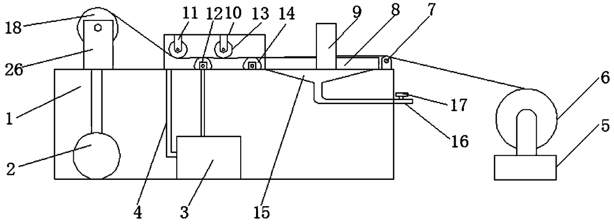
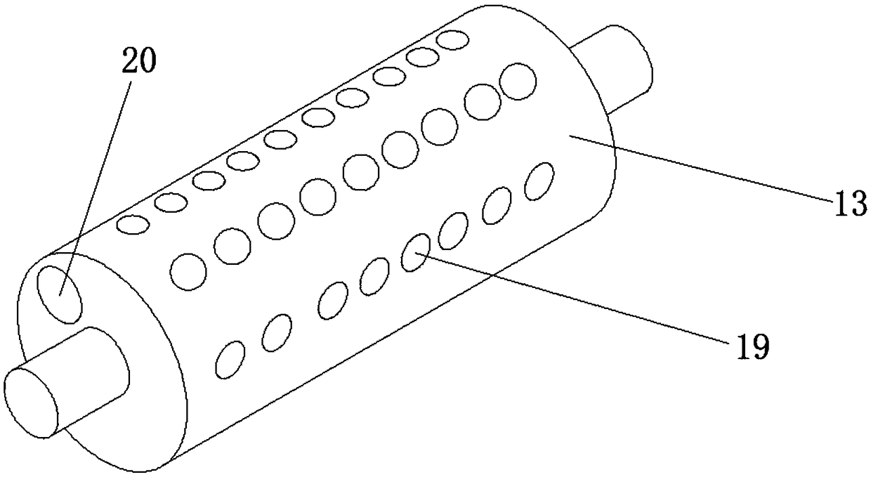
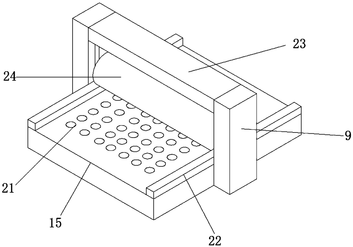
[0018] The present invention provides such Figure 1-4 A clothing cloth drying device shown includes a workbench 1, a feeding roller 6, a receiving roller 18, a drying chamber 10 and an extruding table 8, the feeding roller 6 is fixed on the storage rack 5, and the feeding roller 6 It is rotatably connected with the support rods on both sides of the upper end surface of the storage rack 5, and the storage rack 5 is fixed on the right side of the workbench 1, a...


PUM


Abstract

The invention discloses a garment cloth drying device. The garment cloth drying device comprises a workbench, a feed roller, a material collecting roller, a drying chamber and an extrusion platform, wherein the feed roller is fixed to a storage rack, the feed roller is rotatably connected with support rods on both sides of the upper end surface of the storage rack, the storage rack is fixed to theright side of the workbench, a guide rotating shaft, the extrusion platform, the drying chamber and a fixed frame are arranged on the upper end surface of the workbench in sequence from right to left, the guide rotating shaft is fixedly installed on the right end of the upper end surface of the workbench, the guide rotating shaft is rotatably connected with the workbench, the extrusion platform is of a cuboid structure, fixed rods are vertically fixed to both sides of the extrusion platform respectively, the bottom ends of the fixed rods are fixed to the workbench, the left side of the extrusion platform is close to the drying chamber, and the right side of the extrusion platform is close to the guide rotating shaft. According to the cloth drying device for garment processing, the upper and lower sides of cloth are dried at the same time, so that water in the cloth can be quickly and thoroughly removed, the drying time is saved, and the drying efficiency is improved.

Description

technical field [0001] The invention belongs to the technical field of garment processing, and in particular relates to a garment cloth drying device. Background technique [0002] In the process of garment processing and production, the fabrics used in garment processing need to be cleaned, printed and dyed, dried and other processes. Drying the fabrics is an indispensable process in the production of fabrics. The existing drying devices mainly include square ovens. The electric heater in the oven, the cloth passes through the oven, and the heat generated by the electric heater is used to heat and dry the cloth. With this structure, due to the use of a square oven, the area to be heated in the oven is large, and the electric heating needs to be increased. At the same time, when the fabric has too much moisture, the drying speed is too slow and the drying efficiency is low. At the same time, the drying temperature is too high and it will damage the fabric. Contents of the ...

Claims


Application Information

Patent Timeline
Patent Type & Authority Applications(China)
IPC IPC(8): F26B13/14F26B13/28F26B13/16F26B21/00
CPCF26B13/14F26B13/16F26B13/28F26B21/004D06B15/00D06B15/02D06B23/023D06B23/025D06B23/028D06B23/04
Inventor 柳晓燕
Owner 柳晓燕
Why Eureka
Try Eureka