
Electric power equipment defect analysis device

A defect analysis and power equipment technology, applied in the direction of measuring devices, measuring electricity, measuring electrical variables, etc., can solve problems that are not easy to be found, electromagnetic wave interference of the power grid, etc., and achieve the effect of convenient operation and simple and reasonable overall structure

Inactive Publication Date: 2018-10-26
DAISHAN POWER SUPPLY CO STATE GRID ZHEJIANG ELECTRIC POWER CO +2
View PDF0 Cites 3 Cited by
  • Summary
  • Abstract
  • Description
  • Claims
  • Application Information

AI Technical Summary

Problems solved by technology

[0002] In power equipment such as insulators, power cables, switches, busbars, etc., the corona, electric traces, and arcs generated by early defects are relatively light, and are often not easy to be found, because these equipment will not produce obvious corona discharge. The discharge sound wave, the uncertain approximate position is a little far away, it is difficult to be received by the ultrasonic wave, but these slight equipment defects will generate large electromagnetic wave interference in the power grid

Method used


Image

  • Electric power equipment defect analysis device
  • Electric power equipment defect analysis device

Examples


Embodiment Construction

[0022] The technical solution of the present invention will be further described in detail below in conjunction with the accompanying drawings.

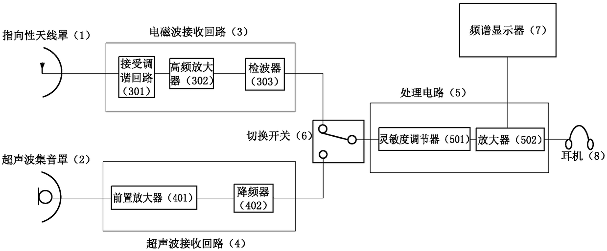
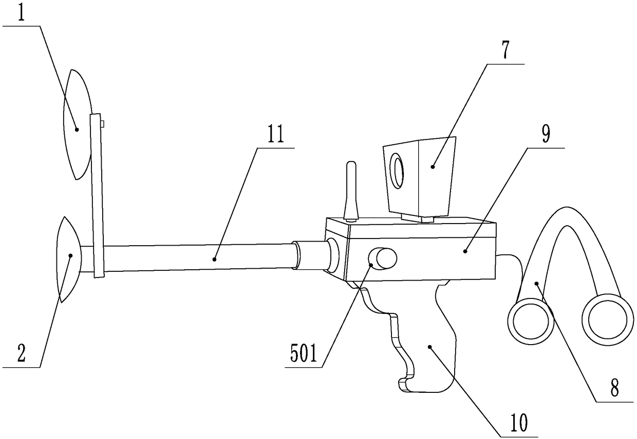
[0023] like Figure 1-2 As shown, the power equipment defect analysis device includes an electromagnetic wave receiving circuit 3, an ultrasonic receiving circuit 4, a processing circuit 5, a directional radome 1, and an ultrasonic sound collecting cover 2; the ultrasonic sound collecting cover 2 is connected to the input end of the electromagnetic wave receiving circuit 3 to Determine the position in the direction of the source of the electromagnetic wave; the ultrasonic sound collecting cover 2 is connected to the input end of the ultrasonic receiving circuit 4 to determine the position in the direction of the source of the ultrasonic wave.

[0024] In order to realize the unified processing of the signals of the electromagnetic wave receiving circuit 3 and the ultrasonic receiving circuit 4, a switch 6 is also included. The elect...


PUM


Abstract

The invention discloses an electric power equipment defect analysis device, and relates to the field of electric power equipment detection. By the aid of the electric power equipment defect analysis device, the problems of frequent difficulty in discovering slight electric corona, tracking and electric arc generated by early defects of electric power equipment and severe electromagnetic interference in power grids can be solved. The electric power equipment defect analysis device comprises an electromagnetic receiving loop, an ultrasonic receiving loop, a processing circuit, a directional antenna housing and an ultrasonic sound collection cover. The ultrasonic sound collection cover is connected with an input end of the electromagnetic receiving loop, so that the directions and the locations of electromagnetic sources can be determined; the ultrasonic sound collection cover is connected with an input end of the ultrasonic receiving loop, so that the directions and the locations of ultrasonic sources can be determined. According to the technical scheme, the electric power equipment defect analysis device has the advantages that the directions and the locations of the electromagneticsources can be determined by the directional antenna housing and the electromagnetic receiving loop, the directions and the locations of the ultrasonic sources can be determined by the ultrasonic sound collection cover and the ultrasonic receiving loop, accordingly, the nearest locations of faults can be determined, and the properties of defects can be judged; equipment with minor defects can beaccurately and quickly searched and judged.

Description

technical field [0001] The invention relates to the field of electric equipment detection, in particular to an electric equipment defect analysis device. Background technique [0002] In power equipment such as insulators, power cables, switches, busbars, etc., the corona, electric traces, and arcs generated by early defects are relatively light, and are often not easy to be found, because these equipment will not produce obvious corona discharge. The discharge sound waves, the uncertain approximate position is a little far away, and it is difficult to be received by the ultrasonic waves, but these slight equipment defects will generate large electromagnetic wave interference in the power grid. Contents of the invention [0003] The technical problem to be solved and the technical task proposed by the present invention are to perfect and improve the existing technical solutions, and to provide a defect analysis device for electric equipment, with the purpose of realizing t...

Claims


Application Information

Patent Timeline
IPC IPC(8): G01R31/00
CPCG01R31/00
Inventor 贺伟军蔡雄翁琪缪武林李海齐袁娜丁鲁浙戴树雅胡炯施徳州方旭丁张叶崔立卿刘伟杨立张相贺王松华李海任军
Owner DAISHAN POWER SUPPLY CO STATE GRID ZHEJIANG ELECTRIC POWER CO
Learn More