Current Predictive Resonant Control Method of Permanent Magnet Motor Based on Disturbance Observer
A technology of disturbance observer and current prediction, applied in motor generator control, electronic commutation motor control, control of electromechanical brakes, etc., can solve the problem that disturbance cannot be completely suppressed.
- Summary
- Abstract
- Description
- Claims
- Application Information
AI Technical Summary
Problems solved by technology
Method used
Image
Examples
Embodiment 1
[0045] Current Predictive Resonance Control Method for Permanent Magnet Motors Based on Disturbance Observer, see figure 1 , the method includes the following steps:
[0046] 101: Establish a continuous model considering periodic and non-periodic disturbances, and establish a motor discretization model based on this model;
[0047] 102: Design an observer-based current predictive resonant controller based on a discretized motor model;
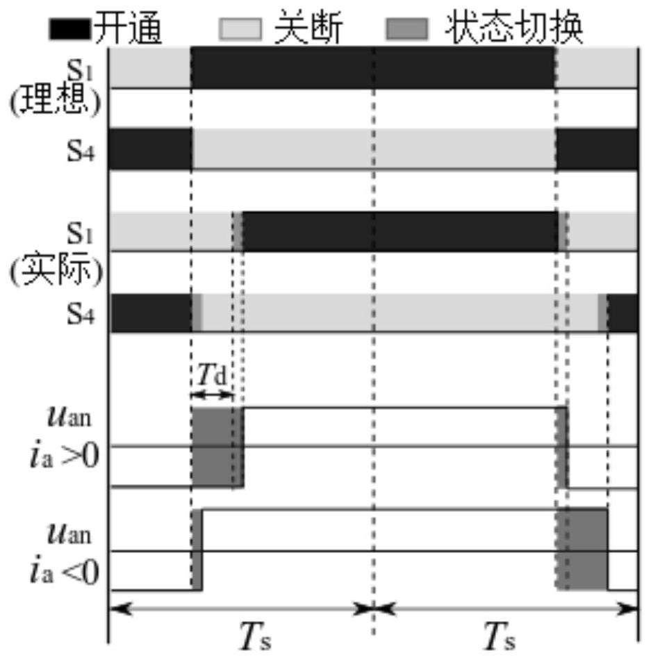
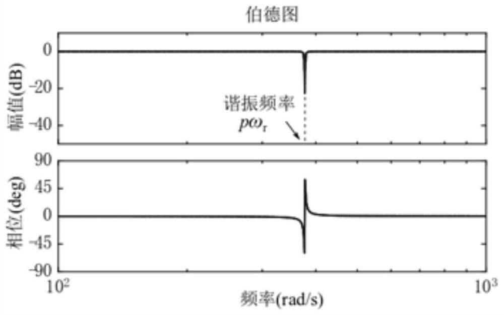
[0048] Firstly, analyze the periodic disturbance caused by the dead time of the inverter and the distribution of flux linkage and establish a periodic disturbance model. In order to suppress the periodic disturbance, a motor model with an embedded resonant controller is established based on the discretization model of the motor;
[0049] Secondly, analyze the aperiodic disturbance caused by parameter mismatch, etc., and design a disturbance observer to observe the disturbance;
[0050] Finally, according to the predicted state and the actual ...
Embodiment 2
[0056] The scheme in embodiment 1 is further introduced below in conjunction with specific calculation formulas and examples, see the following description for details:
[0057] 201: Establish a motor discretization model considering periodic and non-periodic disturbances and control delays;
[0058] Among them, when considering periodic and non-periodic disturbances, the continuous model of surface-mounted permanent magnet motor can be expressed as:
[0059]
[0060] In the formula, i s = i d +ji q , u s = u d +ju q are stator current vector and stator voltage vector respectively; i d i q are the d-axis and q-axis components of the stator current vector; u d , u q are the d-axis and q-axis components of the stator voltage vector; ω m is the rotor electrical angular velocity; R s and L s They are permanent magnet flux linkage, stator resistance and inductance; γ and w represent periodic and non-periodic disturbances, respectively. Unless otherwise specified, ...
PUM
 Abstract
Description
Claims
Application Information
 - R&D
- Intellectual Property
- Life Sciences
- Materials
- Tech Scout
- Unparalleled Data Quality
- Higher Quality Content
- 60% Fewer Hallucinations
Browse by: Latest US Patents, China's latest patents, Technical Efficacy Thesaurus, Application Domain, Technology Topic, Popular Technical Reports.
© 2025 PatSnap. All rights reserved.Legal|Privacy policy|Modern Slavery Act Transparency Statement|Sitemap|About US| Contact US: help@patsnap.com


