Periodic disturbance dual-loop forecast suppression method of permanent-magnet synchronous motor
A permanent magnet synchronous motor, disturbance suppression technology, applied in motor control, motor generator control, electronic commutation motor control, etc. performance and other issues, to achieve the effect of fast and smooth transient performance, dynamic response characteristics and steady-state performance guarantee, and strong robustness
- Summary
- Abstract
- Description
- Claims
- Application Information
AI Technical Summary
Problems solved by technology
Method used
Image
Examples
Embodiment 1
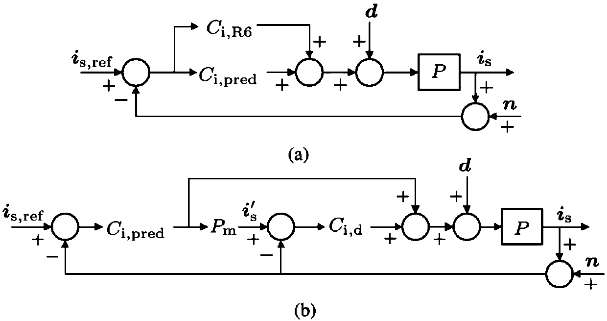
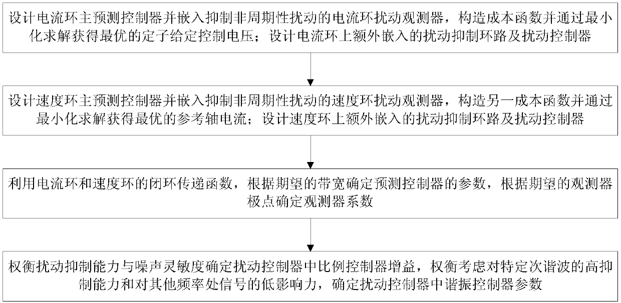
[0064] The embodiment of the present invention proposes a dual-loop predictive control structure, and a dual-loop predictive controller is designed in the current loop and the speed loop respectively (that is, in addition to the loop where the main predictive controller is located, the embodiment of the present invention is also provided with an additional disturbance suppression loop, these two loops constitute a double-loop structure, the double-loop structure is applied in the speed loop and the current loop respectively), which effectively suppresses the periodic disturbance, and can not affect the main controller while suppressing the disturbance, that is, the prediction The original given tracking capability of the controller realizes the decoupling of given tracking and periodic disturbance suppression.
[0065] Among them, the given tracking performance is only determined by the main predictive controller, and the disturbance suppression performance is determined by the...
Embodiment 2
[0073] Combined with the specific calculation formula, the appended Figure 1-4 1. Examples further introduce the scheme in Example 1, see the following description for details:
[0074] 1. Modeling of permanent magnet synchronous motor system
[0075] In the embodiment of the present invention, the model of the permanent magnet synchronous motor is divided into two parts, the current loop and the speed loop. In the current loop, select the stator current vector i s As the state variable, the current loop model is obtained:
[0076]
[0077] In the formula, R s is the stator resistance, L s is the stator inductance, u c is the stator voltage vector, is the permanent magnet flux linkage, ω e is the rotor electrical angular frequency.
[0078] Discretize the formula (1) to obtain the state space expression of the current loop model in the discrete domain:
[0079]
[0080] In the formula,
[0081]
[0082] Among them, T s Indicates the sampling period, and η...
Embodiment 3
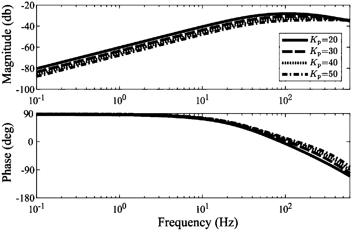
[0180] Combine below Figure 5-Figure 8 The scheme in embodiment 1 and 2 is carried out feasibility verification, see the following description for details:
[0181] In the embodiment of the present invention, taking the current loop as an example, the given tracking characteristics of the double-loop control structure and the parallel control structure are compared. The given tracking performance of the double-loop controller and the parallel controller is as follows: Figure 5 shown. When the parallel structure is used for current control, the signal at or near the resonant frequency is amplified or reduced, and this phenomenon is caused by the inherent cut-off frequency ω of the resonant controller l caused. Due to these fluctuations, the transient response exhibits significant oscillations when a step change occurs in the given signal. Adopting a parallel periodic disturbance suppression strategy will reduce the given tracking performance of the main predictive control...
PUM
 Abstract
Description
Claims
Application Information
 - R&D
- Intellectual Property
- Life Sciences
- Materials
- Tech Scout
- Unparalleled Data Quality
- Higher Quality Content
- 60% Fewer Hallucinations
Browse by: Latest US Patents, China's latest patents, Technical Efficacy Thesaurus, Application Domain, Technology Topic, Popular Technical Reports.
© 2025 PatSnap. All rights reserved.Legal|Privacy policy|Modern Slavery Act Transparency Statement|Sitemap|About US| Contact US: help@patsnap.com


