
Tracking type solar cell panel with adjustable area

A solar panel and tracking technology, which is applied to solar thermal energy, solar collectors, solar heating systems, etc., can solve problems such as complex methods, inability to accurately control the effective radiation area of ​​sunlight, and inability to accurately control energy supply, etc., to achieve The effect of reducing power generation

Inactive Publication Date: 2018-10-26
广州引航全水科技有限公司
View PDF15 Cites 1 Cited by
  • Summary
  • Abstract
  • Description
  • Claims
  • Application Information

AI Technical Summary

Problems solved by technology

[0002] As a sustainable source of energy, solar energy is favored by people in modern society. However, affected by the autobiography of the earth, the direction and intensity of the sun at the same location change gradually over time. How to make full use of sunlight It is a problem that people have been pursuing and being forced to solve; invention application number: 201020037753.7, name: sun-facing solar cooker that automatically synchronizes with the sun's movement. When the sun is shining and the energy is sufficient, deflect the stove in one direction to avoid the sun, so as to rely solely on the battery for power supply. The method is complicated, and the energy supply cannot be adjusted by adjusting the effective radiation area of ​​the sun according to the needs, and the sun cannot be accurately controlled. The effective radiation area of ​​light, so that the energy supply cannot be precisely controlled

Method used


Image

  • Tracking type solar cell panel with adjustable area
  • Tracking type solar cell panel with adjustable area
  • Tracking type solar cell panel with adjustable area

Examples


Embodiment Construction

[0023] The present invention will be further described in detail below in conjunction with the embodiments and the accompanying drawings, but the embodiments of the present invention are not limited thereto.

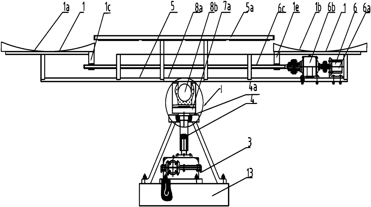
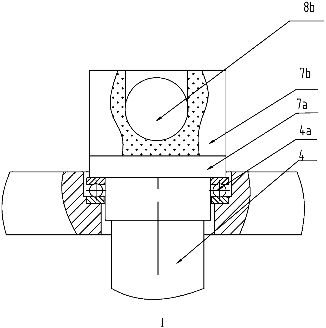
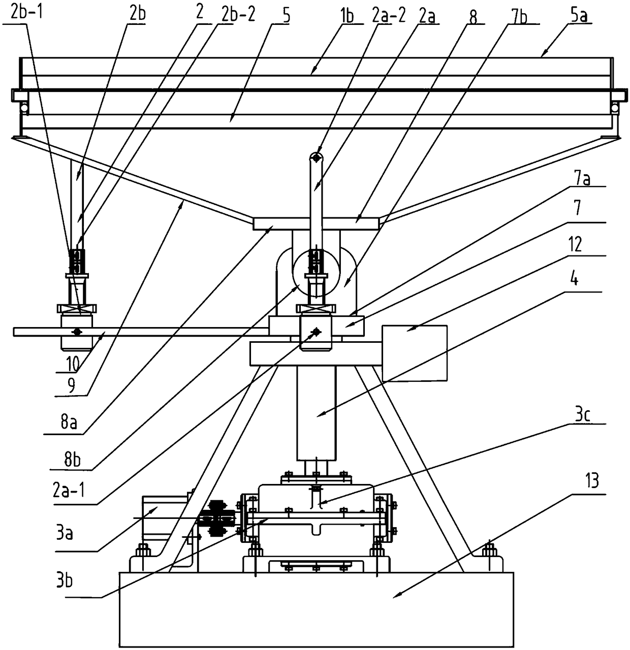
[0024] Such as figure 1 The area-adjustable and tracking solar panel shown includes a solar panel 1, an elevation adjustment device 2 and a rotation device 3. The rotation device 3 drives the solar panel 1 to rotate through a vertical shaft 4, and the elevation adjustment device 2 To adjust the elevation angle of the solar panel 1, first adjust the elevation angle of the solar panel 1 through the elevation adjustment device 2 to adapt to the height of the sun at different times, and then adjust the solar panel 1 through the rotating device 3 to adapt to the direction of sunlight relative to the panel.

[0025] The solar panel 1 includes two groups of panels distributed on the same straight line: a panel 1a and a panel 1b, the two groups of panels slide relative to each o...


PUM


Abstract

The invention discloses a tracking type solar cell panel with an adjustable area. The solar cell panel comprises a solar cell panel, an elevation adjusting device and a rotating device, wherein the rotating device drives the solar cell panel to rotate through a vertical shaft, the elevation adjusting device adjusts the elevation of the solar cell panel, the solar cell panel comprises two groups ofcell panels distributed on the same straight line, two groups of cell panels relatively slide on a horizontal bearing rack; the horizontal bearing rack and the vertical shaft are in universal connection, sun shield which is higher than the plane located by two groups of cell panels is arranged on the horizontal bearing rack; the elevation adjusting device comprises a front-back elevation adjusting device and a left-right elevation adjusting device, wherein the included angle between the axis connecting line and each of the front-back elevation adjusting device and the left-right elevation adjusting device is 90 DEG, the front-back elevation adjusting device is used for adjusting the front-back elevation of the horizontal bearing rack, and the left-right elevation adjusting device is usedfor adjusting the left-right elevation of the horizontal bearing rack. The whole cell panel disclosed by the invention is simple in structure, the solar cell panel angle can be adjusted according to the sun direction, and the lighting area of the solar cell panel can be adjusted.

Description

technical field [0001] The invention relates to a solar battery panel, in particular to a tracking type solar battery panel which can adjust the solar radiation area. Background technique [0002] As a sustainable source of energy, solar energy is favored by people in modern society. However, affected by the autobiography of the earth, the direction and intensity of the sun at the same location change gradually over time. How to make full use of sunlight It is a problem that people have been pursuing and being forced to solve; invention application number: 201020037753.7, name: sun-facing solar cooker that automatically synchronizes with the sun's movement. When the sun is shining and the energy is sufficient, deflect the stove in one direction to avoid the sun, so as to rely solely on the battery for power supply. The method is complicated, and the energy supply cannot be adjusted by adjusting the effective radiation area of ​​the sun according to the needs, and the sun can...

Claims


Application Information

Patent Timeline
IPC IPC(8): H02S20/32F24S25/70F24S30/40
CPCH02S20/32Y02E10/50
Inventor 卢丽菊
Owner 广州引航全水科技有限公司
Learn More