
Non-contact ultrasonic thickness gauge with high detection precision

A non-contact, detection accuracy technology, applied in the direction of using ultrasonic/sonic/infrasonic waves, instruments, measuring devices, etc., can solve the problems of contact surface wear, detection failure, incorrect display, etc., to improve practicability and eliminate rust. , The effect of preventing wear

Active Publication Date: 2018-10-30
山东天厚石油科技有限责任公司
View PDF7 Cites 9 Cited by
  • Summary
  • Abstract
  • Description
  • Claims
  • Application Information

AI Technical Summary

Problems solved by technology

[0003] During the use of existing ultrasonic thickness gauges, in order to ensure that the detection surface of the probe is parallel to the surface of the workpiece, the probe is usually attached to the workpiece for detection, but this will cause the contact surface of the probe to wear, and it will be damaged after long-term use. The surface roughness increases, resulting in a decrease in sensitivity and incorrect display. Not only that, but when detecting some workpieces with rusted surfaces, the coupling effect between the probe and the contact surface is poor and the reflection echo is low due to the excessive surface roughness of the workpiece. , even the echo signal cannot be received, resulting in detection failure, thereby reducing the practicability of the existing ultrasonic thickness gauge

Method used


Image

  • Non-contact ultrasonic thickness gauge with high detection precision
  • Non-contact ultrasonic thickness gauge with high detection precision
  • Non-contact ultrasonic thickness gauge with high detection precision

Examples


Embodiment Construction

[0024] The present invention is described in further detail now in conjunction with accompanying drawing. These drawings are all simplified schematic diagrams, which only illustrate the basic structure of the present invention in a schematic manner, so they only show the configurations related to the present invention.

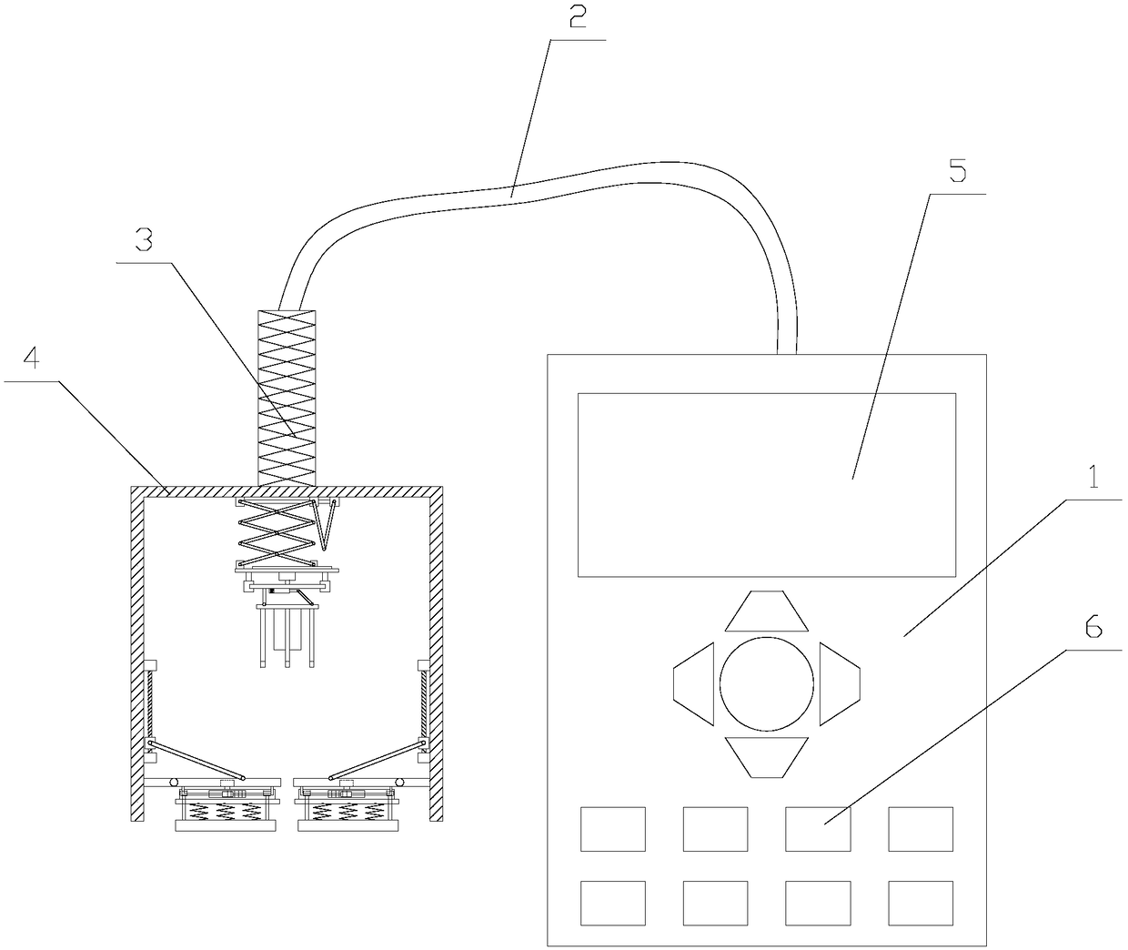
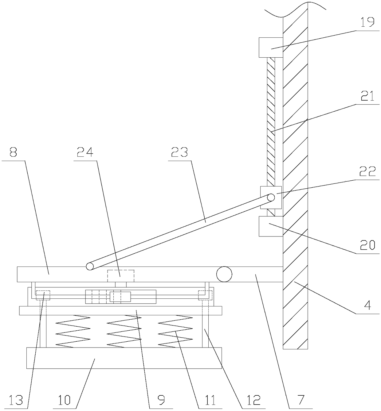
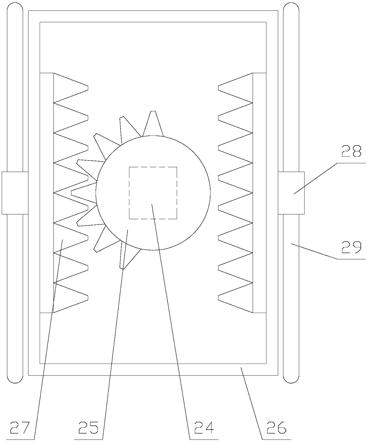
[0025] like figure 1 As shown, a non-contact ultrasonic thickness gauge with high detection accuracy includes a host 1, a connecting wire 2, a handle 3 and a detection box 4. The host 1 is provided with a display screen 5 and several buttons 6. The The main body is provided with a PLC, the buttons 6 and the display screen 5 are electrically connected to the PLC, the host 1 is connected to the handle 3 through the connecting wire 2, the handle 3 is fixedly connected to the detection box 4, and the detection box 4 is provided with an opening on the side away from the grip bar 3, and the detection box 4 is provided with a detection mechanism and two grinding mec...


PUM


Abstract

The invention relates to a non-contact ultrasonic thickness gauge with high detection precision. The non-contact ultrasonic thickness gauge comprises a main unit, a connecting line, a holding rod anda detection box; the detection box is internally provided with a detection mechanism and two polishing mechanisms, each polishing mechanism comprises a side plate, a shrinking plate, a shrinking assembly, a reciprocating assembly, a reciprocating plate and a polishing assembly, each polishing assembly comprises a polishing block, a plurality of springs and two orientation units, each orientation unit comprises an orientation rod and a bump, and the detection mechanism comprises a lifting assembly, a lifting plate, a steering assembly, a steering plate, a probe and a plurality of contact rods.According to the non-contact ultrasonic thickness gauge with the high detection precision, the polishing blocks move back and forth on the surface of a workpiece through the polishing mechanisms, ruston the workpiece is eliminated, the workpiece is restored to be smooth, and the detection is facilitated; moreover, the direction of the probe is adjusted through the detection mechanism so that theprobe can be aligned with the workpiece, the probe is prevented from wear while the detection precision is improved, the service life of the probe is prolonged, and the practicability of the gauge isimproved.

Description

technical field [0001] The invention relates to the field of ultrasonic detection equipment, in particular to a non-contact ultrasonic thickness gauge with high detection accuracy. Background technique [0002] The ultrasonic thickness gauge measures the thickness according to the principle of ultrasonic pulse reflection. When the ultrasonic pulse emitted by the probe passes through the object to be measured and reaches the interface of the material, the pulse is sent back to the probe. By accurately measuring the propagation time of the ultrasonic wave in the material, the Determine the thickness of the material being measured. Ultrasonic thickness gauges can measure the thickness of various pipes and pressure vessels in production equipment, detect their degree of thinning after being corroded during use, and can also accurately measure various plates and various processed parts. [0003] During the use of existing ultrasonic thickness gauges, in order to ensure that the ...

Claims


Application Information

Patent Timeline
Patent Type & Authority Applications(China)
IPC IPC(8): G01B17/02
CPCG01B17/02
Inventor 吴键斌
Owner 山东天厚石油科技有限责任公司
Learn More