Permanent magnet synchronous motor for weakening cogging torque of built-in permanent magnet motor
A permanent magnet motor and cogging torque technology, which is applied to synchronous motors with stationary armatures and rotating magnets, synchronous machines, synchronous machine parts, etc., can solve the problem of difficult optimization of pole arcs, large cogging torque, etc. problems, to achieve the effect of improving dynamic performance, suppressing cogging torque, and suppressing vibration and noise
- Summary
- Abstract
- Description
- Claims
- Application Information
AI Technical Summary
Problems solved by technology
Method used
Image

Examples
Embodiment 1
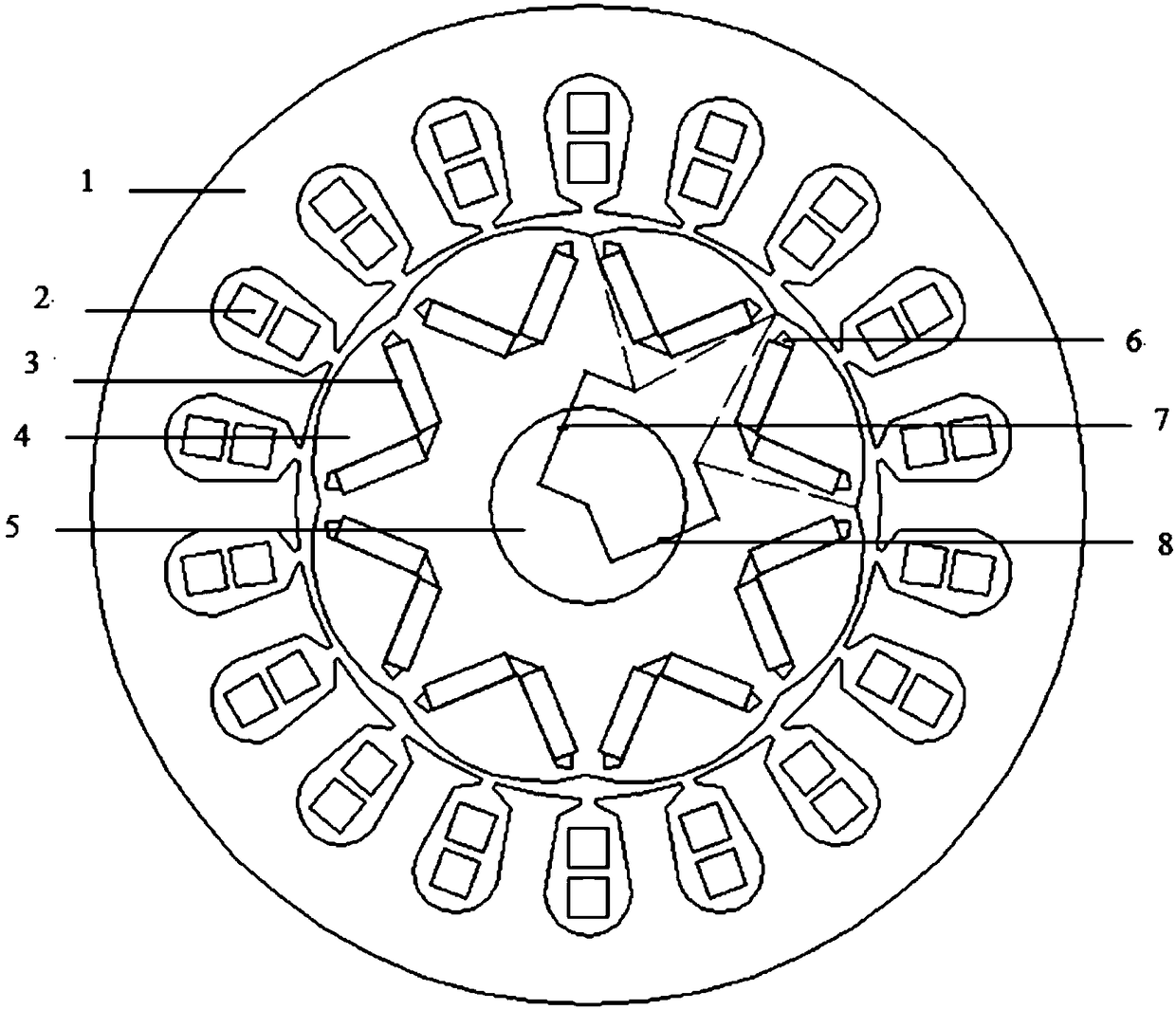
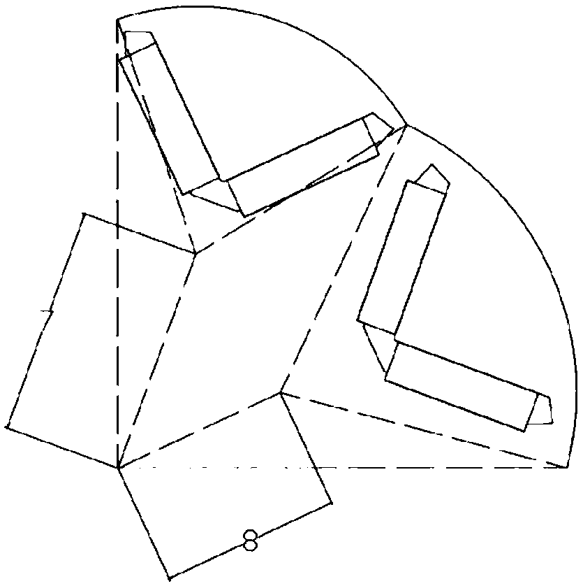
[0025] Such as figure 1 with figure 2 As shown, the permanent magnet synchronous motor that weakens the cogging torque of the interior permanent magnet motor, figure 1 The dotted line intersection point is the center of the arc. Including the stator, the casing outside the stator, the end covers at both ends of the casing, the motor shaft 5 and the rotor 4, the motor shaft 5 passes through the rotor 4 and is fixed with the rotor 4, the rotor 4 is located inside the ring-shaped stator, and the stator includes The stator core 1 and the motor winding 2, the stator core 1 has a stator slot, the motor winding 2 is wound on the stator slot of the stator core 1, the rotor 4 includes an even number of permanent magnet poles, and two adjacent permanent magnets A pair of magnetic poles; two permanent magnets 3 are arranged in the permanent magnet magnetic poles, and magnetic isolation bridges 6 are arranged at both ends of the permanent magnets 3, and the interior of the magnetic iso...
Embodiment 2
[0028] A permanent magnet synchronous motor that weakens the cogging torque of a built-in permanent magnet motor, including a stator, a casing outside the stator, end covers at both ends of the casing, a motor shaft 5 and a rotor 4, and the motor shaft 5 passes through the rotor 4 and connects to the rotor 4 Fixed together, the rotor 4 is located inside the ring-shaped stator. The stator includes a stator core 1 and a motor winding 2. The stator core 1 has a stator slot, and the motor winding 2 is wound on the stator slot of the stator core 1. The rotor 4 There are even pairs of permanent magnet poles, and two adjacent permanent magnet poles are a pair; two permanent magnets 3 are arranged in the permanent magnet poles, and the two ends of the permanent magnets 3 are provided with a magnetic isolation bridge 6, and a magnetic isolation bridge 6 Inside is air. The two permanent magnets 3 are "V"-shaped, and the polarities in the radial direction of the "V"-shaped cross-section ...
Embodiment 3
[0031] A permanent magnet synchronous motor that weakens the cogging torque of a built-in permanent magnet motor, including a stator, a casing outside the stator, end covers at both ends of the casing, a motor shaft 5 and a rotor 4, and the motor shaft 5 passes through the rotor 4 and connects to the rotor 4 Fixed together, the rotor 4 is located inside the ring-shaped stator. The stator includes a stator core 1 and a motor winding 2. The stator core 1 has a stator slot, and the motor winding 2 is wound on the stator slot of the stator core 1. The rotor 4 There are even pairs of permanent magnet poles, and two adjacent permanent magnet poles are a pair; two permanent magnets 3 are arranged in the permanent magnet poles, and the two ends of the permanent magnets 3 are provided with a magnetic isolation bridge 6, and a magnetic isolation bridge 6 The interior is filled with ceramic material and bonded. The two permanent magnets 3 are "V"-shaped, and the polarities in the radial ...
PUM
 Abstract
Description
Claims
Application Information
 - R&D
- Intellectual Property
- Life Sciences
- Materials
- Tech Scout
- Unparalleled Data Quality
- Higher Quality Content
- 60% Fewer Hallucinations
Browse by: Latest US Patents, China's latest patents, Technical Efficacy Thesaurus, Application Domain, Technology Topic, Popular Technical Reports.
© 2025 PatSnap. All rights reserved.Legal|Privacy policy|Modern Slavery Act Transparency Statement|Sitemap|About US| Contact US: help@patsnap.com