Mop handle convenient to hang
A handle and mop technology, which is applied in cleaning carpets, floors, cleaning equipment, etc., can solve the problem of destroying the integrity of the wall, and achieve the effect of compact structure and slowing down the emission of water
Inactive Publication Date: 2018-11-02
贵州好能手日用品商贸有限公司
View PDF6 Cites 0 Cited by
- Summary
- Abstract
- Description
- Claims
- Application Information
AI Technical Summary
Problems solved by technology
[0005] The present invention intends to provide a mop handle that is easy to hang, so as to solve the technical problem of destroying the integrity of the wall caused by punching holes in the wall to hang the mop on the wall in the prior art
Method used
View moreImage
Smart ImageViewing Examples
Examples
Embodiment Construction
[0017] Further detailed explanation through specific implementation mode below:
Login to View More PUM
 Abstract
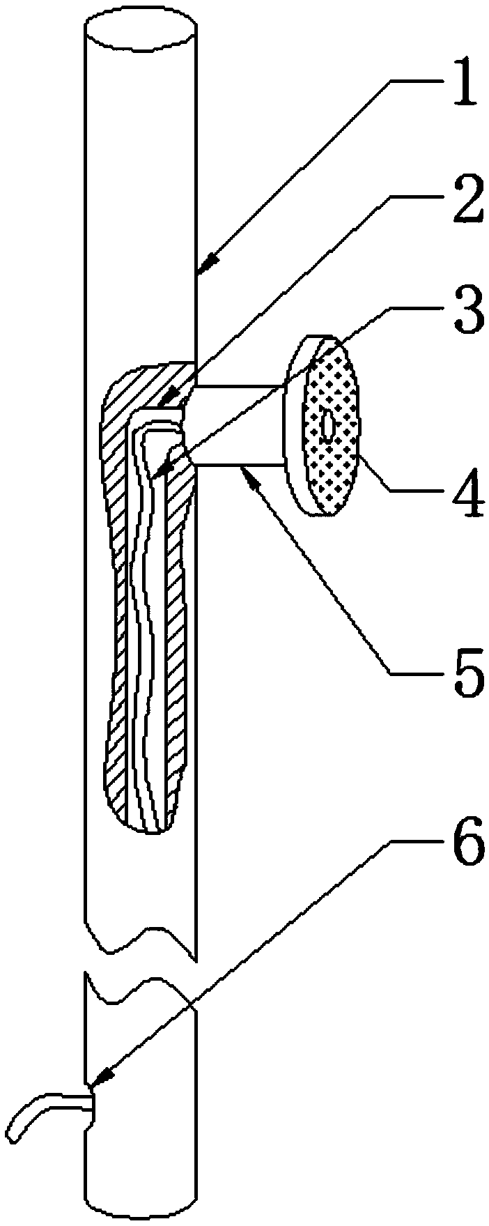
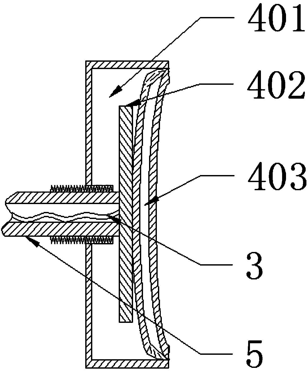
The invention discloses a mop handle convenient to hang in the field of household articles. The mop handle comprises a handle body and a vacuum chuck. The side wall, in contact with a wall face, of the vacuum chuck is uniformly provided with a plurality of through holes, a soft pad is arranged in the vacuum chuck and divides the inside of the vacuum chuck into a first cavity layer and a second cavity layer, and the through holes are communicated with the second cavity layer. The side wall of the side, opposite to the through holes, of the vacuum chuck is provided with a connecting hole. A connecting rod is vertically and rotatably connected to the handle body, a push plate is connected to the end, away from the handle body, of the connecting rod and is perpendicular to the connecting rod,the connecting rod is in threaded connection with the connecting hole, and the push plate is located in the first cavity layer. According to the scheme, the current vacuum chuck is arranged on the handle body after being modified, and a mop is firmly fixed to the wall face. Compared with the prior art, nails driven into a wall are not needed and wall face integrity is not destroyed when the mop handle is hung on the wall.
Description
technical field [0001] The invention relates to the field of furniture articles, in particular to a mop handle which is convenient for hanging. Background technique [0002] The mop is a cleaning tool commonly used in our daily life. It is a long-handled cleaning tool used to scrub the floor. The long handle is also the handle of the mop. When using it, it is necessary to moisten the rag at the front of the handle with water, so that the ground can be easily wiped. Stains come out clean. [0003] The handle of a traditional mop usually does not have a hook or a ring. However, after the mop is used, it needs to be cleaned and then placed to keep the mop clean and hygienic. There is no structure on the handle that can hang the mop in the air. Put it on the railing and let the rag drip dry. This way of placing takes up more space and looks messy. [0004] In this regard, there is now a mop with a hook or a ring on the handle, and the entire mop can be hung vertically on the w...
Claims
Login to View More Application Information
Patent Timeline
 IPC IPC(8): A47L13/20A47L13/512
CPCA47L13/20A47L13/512
Inventor 赵梅
Owner 贵州好能手日用品商贸有限公司
Features
- R&D
- Intellectual Property
- Life Sciences
- Materials
- Tech Scout
- Unparalleled Data Quality
- Higher Quality Content
- 60% Fewer Hallucinations
Learn More Browse by: Latest US Patents, China's latest patents, Technical Efficacy Thesaurus, Application Domain, Technology Topic, Popular Technical Reports.
© 2025 PatSnap. All rights reserved.Legal|Privacy policy|Modern Slavery Act Transparency Statement|Sitemap|About US| Contact US: help@patsnap.com


