Filter cylinder and dust collector

The technology of a dust collector and a filter cartridge is applied to the filter cartridge. , Separation device, dust collector field, can solve the problems of large space required, increase the overall height of the dust collector, affect the dust collection effect, etc., to achieve the effect of guaranteed service life, better vibration effect, and lower technical requirements

Pending Publication Date: 2018-11-02
玉环太平洋机械有限公司
View PDF7 Cites 0 Cited by
  • Summary
  • Abstract
  • Description
  • Claims
  • Application Information

AI Technical Summary

Problems solved by technology

Although this structure can remove the dust on the filter cartridge through vibration, there are also some shortcomings: 1. The dust will settle on the vibration motor, motor bracket and filter cartridge fixing plate, which will affect the dust collection effect and affect the dust collector. Use safety and service life; 2. The environment in the air inlet chamber is relatively harsh, and the technical requirements of the motor are high, so there are problems of high purchase cost of the motor and insufficient service life of the motor; 3. The vibration device is located in the filter cartridge and dust collection The space required between the drawers is relatively large, which is not suitable for refitting the existing dust collector and will increase the overall height of the dust collector compared with the pulse blowback method, which may affect the convenience of the dust collector.

Method used


Image

  • Filter cylinder and dust collector
  • Filter cylinder and dust collector
  • Filter cylinder and dust collector

Examples


Embodiment 1

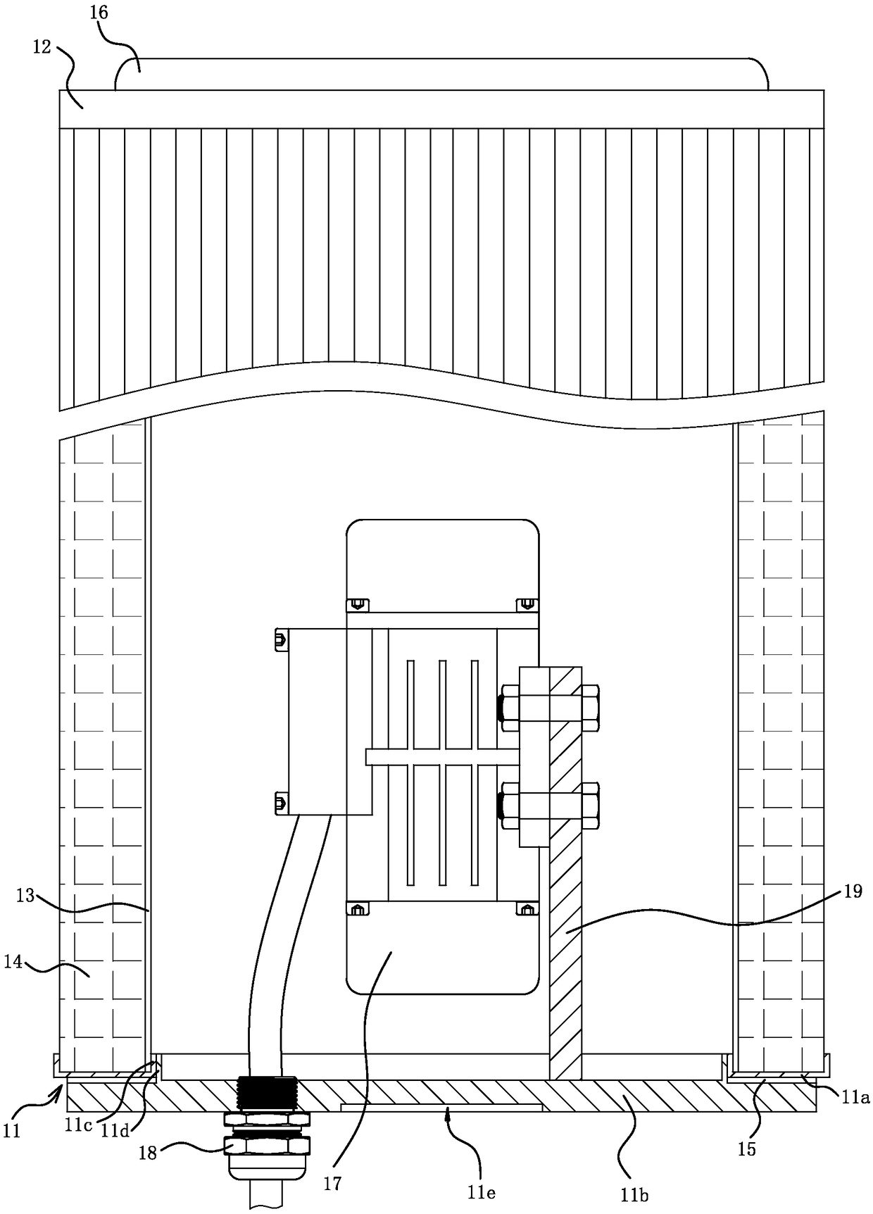
[0024] Such as figure 1 As shown, the filter cartridge 10 includes a bottom plate 11 , a top plate 12 , a liner 13 and a filter cartridge body 14 . The bottom plate 11 includes an annular outer ring 11a and a center plate 11b that can cover the center hole of the outer ring 11a. A sealing sheet 15 is embedded between the outer ring 11a and the center plate 11b. This structure effectively ensures that the outer ring 11a and the center The tightness between the plates 11b prevents dusty air from directly entering the filter cartridge 10 . The inner side of the outer ring 11a has a flange 11c, and the center plate 11b has a positioning bead 11d, the positioning bead 11d is embedded in the center hole of the outer ring 11a, and the flange 11c of the outer ring 11a relies on the positioning bead 11d, thereby limiting The center plate 11b slides to improve the installation stability of the center plate 11b.

[0025] The filter cartridge body 14 is cylindrical, and the top plate 12...

Embodiment 2

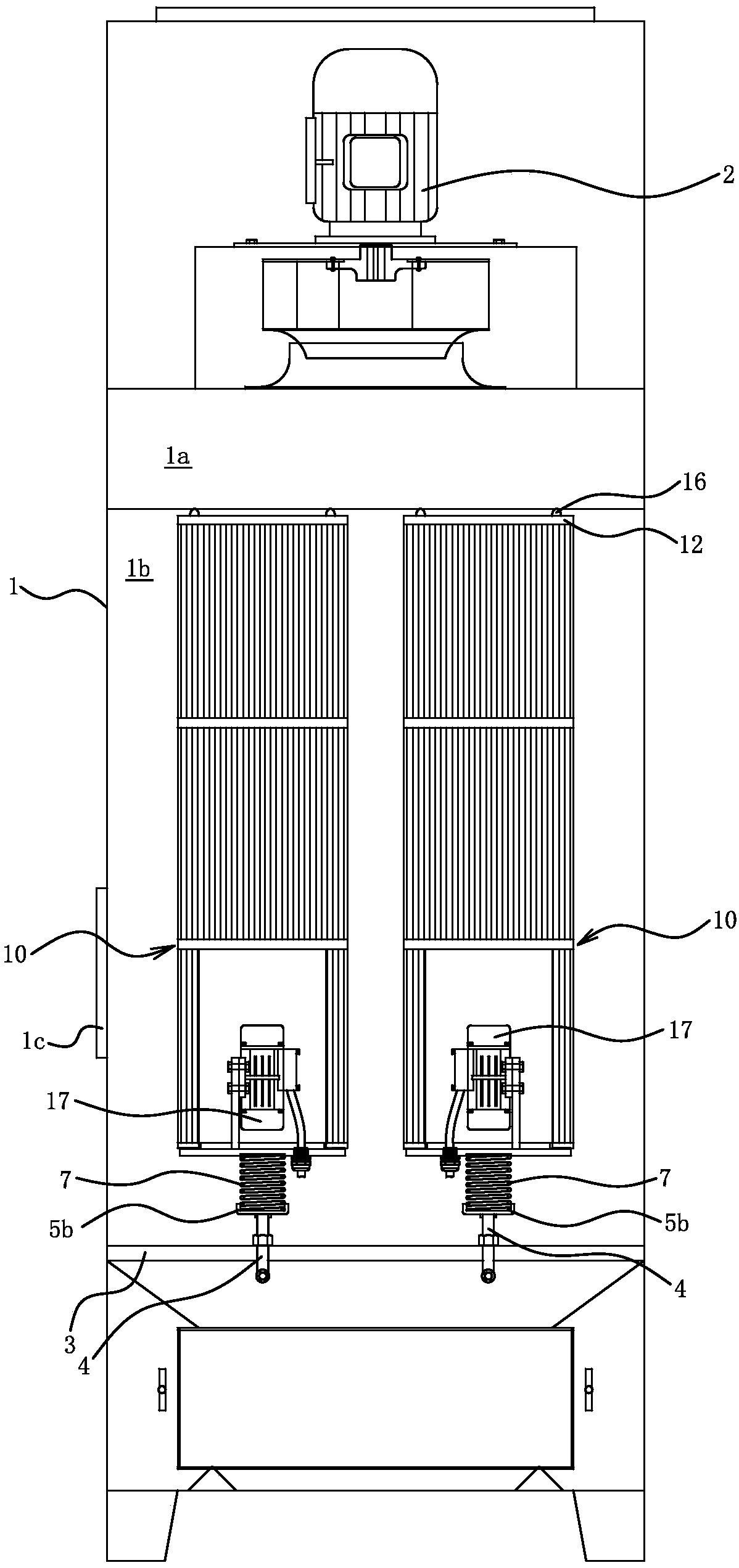
[0034] The structure and principle of this embodiment are basically the same as that of Embodiment 1, and the basic similarities will not be redundantly described, and only the differences will be described, and the differences are as follows: image 3 As shown, the shock absorber 5 can be replaced by the following scheme, the shock absorber 5 includes a spring 7 and a supporting plate 5b. The upper end of the spring 7 abuts against the bottom surface of the central plate 11b, the lower end of the spring 7 is embedded in the supporting plate 5b, and the locking bolt 4 is embedded in the supporting plate 5b; the spring 7 is in a compressed state.

Embodiment 3

[0036] The structure and principle of this embodiment are basically the same as that of Embodiment 1, and the basic similarities will not be redundantly described, and only the differences will be described, and the differences are as follows: Figure 4 As shown, the outer ring 11a and the central plate 11b are connected through a detachable fixed structure; specifically, the outer ring 11a and the central plate 11b are fixedly connected through the feet 11g and fastening bolts 11f; according to the actual situation, the outer ring Screw connection can also be adopted between 11a and central plate 11b.

[0037] The outer side of the top plate 12 has hanging ears 12a, the vibrator 17 is arranged horizontally, and the vibrator 17 is directly installed on the center plate 11b through bolts.

[0038] Such as Figure 5 As shown, there is only one filter cartridge 10 in the dust collector, the inner chamber of the dust collector is not divided into upper chamber 1a and lower chambe...


PUM


Abstract

Belonging to the field of operation technology, the invention provides a filter cylinder and a dust collector, and solves the problems of short service life of the existing dust collectors. The filtercylinder comprises a base plate, a top plate, an inner liner and a filter cylinder body. The filter cylinder body is cylindrical, and the top plate has an opening communicated with the inner cavity of the filter cylinder, the inner liner and the filter cylinder body are located between the base plate and the top plate, one end of the inner liner is connected to the base plate, and the other end of the inner liner is connected to the top plate. The filter cylinder body is internally equipped with a vibrator, and the vibrator is mounted on the base plate. The dust collector comprises a shell and the filter cylinder, an air hole is disposed on the top wall of the inner cavity in the shell, and an air inlet is disposed on a side wall of the shell, the filter cylinder is located in the inner cavity of the shell, the filter cylinder is vertically disposed, and the opening of the filter cylinder is communicated with the air hole, and the filter cylinder and the shell are connected through adetachable fixed structure. The air in the filter cylinder is cleaner relative to the air outside the filter cylinder, thereby lowering the technical requirements of the vibrator and further reducingthe procurement cost of the vibrator.

Description

technical field [0001] The invention belongs to the field of operation technology, and relates to a separation device, in particular to a filter cartridge. [0002] The invention belongs to the field of operation technology, and relates to a separation device, in particular to a dust collector. Background technique [0003] A filter cartridge is a cylindrical element used for filtering, and is generally divided into filter cartridges used to filter gas media and filter liquid media. The filter cartridges that people usually refer to are mostly used to filter gases. [0004] The filter cartridge is a surface filter element, which uses the tiny air-permeable tissue formed on the surface of the filter material to block the particulate matter in the gas. Commonly used automatic cleaning methods for filter cartridges include high-pressure gas pulse blowback and mechanical vibration. Pulse blowback is to use the preset parameters of the controller to give a signal to the soleno...

Claims


Application Information

Patent Timeline
Patent Type & Authority Applications(China)
IPC IPC(8): B01D46/24
CPCB01D46/2411B01D46/76
Inventor 陈美青
Owner 玉环太平洋机械有限公司
Why Eureka
Try Eureka