Novel ultrasonic cleaning machine

A technology of ultrasonic wave and cleaning machine, which is applied to dryers, cleaning methods and utensils, and cleaning methods using liquids, etc., which can solve the problems of incomplete cleaning and low cleaning power of wires, and achieve the effect of reducing labor force

Inactive Publication Date: 2018-11-02
GUANGDONG JINGXUN LIYA SPECIAL WIRE
View PDF5 Cites 0 Cited by
  • Summary
  • Abstract
  • Description
  • Claims
  • Application Information

AI Technical Summary

Problems solved by technology

[0004] Aiming at the deficiencies of the prior art, the present invention provides a new type of ultrasonic cleaning machine, which solves the problem that the existing ultrasonic cleaning machine does not clean the wires well enough and cannot complete the integrated work from cleaning to drying.

Method used


Image

  • Novel ultrasonic cleaning machine
  • Novel ultrasonic cleaning machine
  • Novel ultrasonic cleaning machine

Examples


Embodiment 1

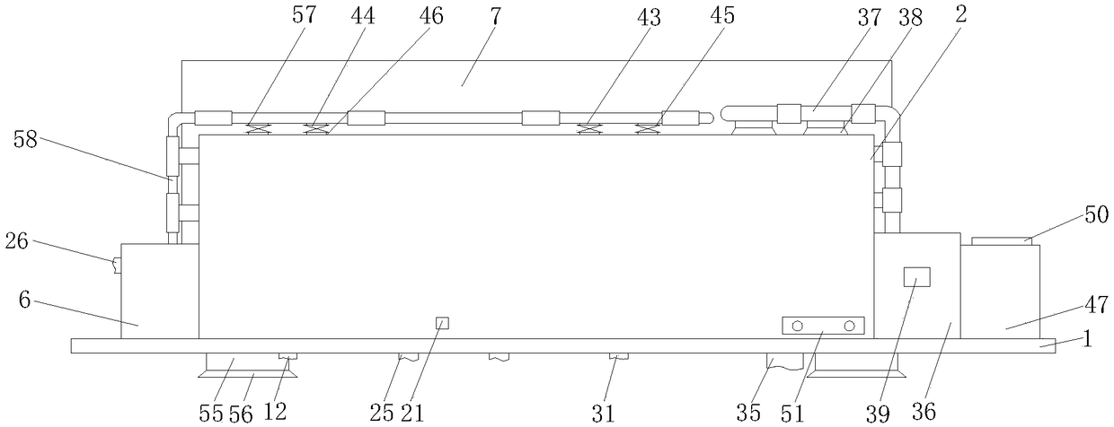
[0033] A new type of ultrasonic cleaning machine, including a bottom plate 1, support legs 55 are fixedly connected to both sides of the bottom of the bottom plate 1, rubber pads 56 are fixedly connected to the bottom of the support legs 55, and the cooperation between the support legs 55 and the rubber pads 56 can prevent the bottom plate from 1 The direct contact with the ground reduces friction and also plays a certain role in buffering and shock absorption, so that the ultrasonic cleaning machine can be used for a long time. The top of the bottom plate 1 and the side of the hot air blower 36 are fixedly connected with a rectangular box 47 , the back side of rectangular box 47 inwalls is fixedly connected with CPU 48, and the model of CPU 48 is ARM9, and the output end of CPU 48 is respectively connected with data comparator 49, water pump 42, the first electromagnetic leakage valve 44 and the 2nd. The input ends of the two electromagnetic leakage valves 45 are connected, an...

Embodiment 2

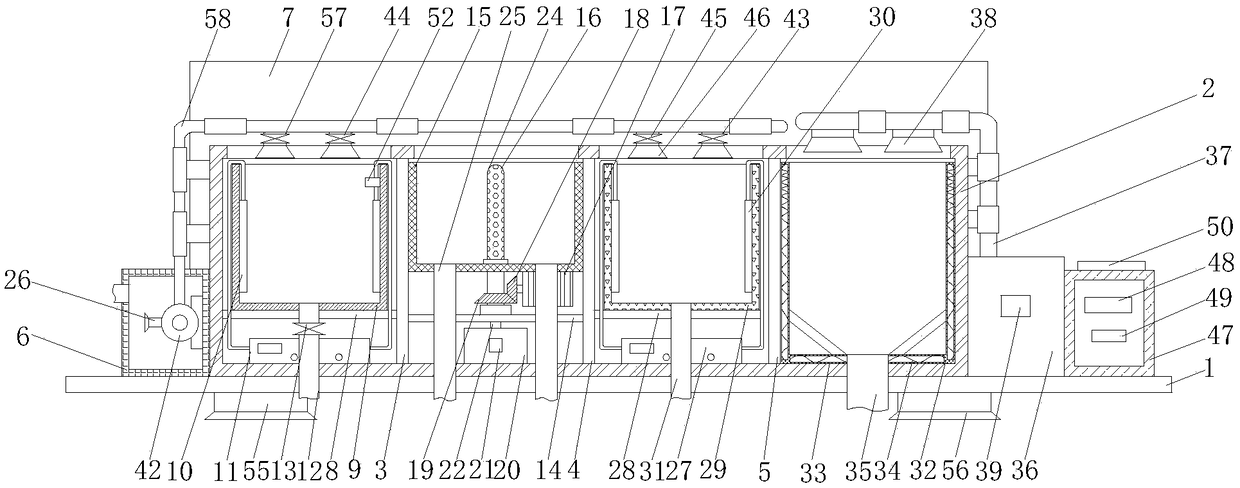
[0035] A new type of ultrasonic cleaning machine, comprising a bottom plate 1, the top of the bottom plate 1 is fixedly connected with an operation frame 2, and the top and bottom of the inner wall of the operation frame 2 are fixedly connected with a vertical plate 3 and a partition in sequence from left to right 4 and a support plate 5, the top of the bottom plate 1 is fixedly connected with a water tank 6 on one side of the operation frame 2, the top of the bottom plate 1 is fixedly connected with a support frame 7 at the back of the operation frame 2, and the operation frame 2 A horizontal plate 8 is fixedly connected between one side of the inner wall and one side of the vertical plate 3, and the top of the horizontal plate 8 is fixedly connected with a cleaning frame 9, and both sides of the inner wall of the cleaning frame 9 are fixedly connected with a first ultrasonic Vibration plate 10, the bottom of the inner wall of the operation frame 2 is fixedly connected with a ...


PUM


Abstract

The invention discloses a novel ultrasonic cleaning machine. The novel ultrasonic cleaning machine comprises a bottom plate, wherein the top of the bottom frame is fixedly connected with an operationframe; a vertical plate, a separation plate and a supporting plate are sequentially and fixedly connected between the top and the bottom of an inner wall of the operation frame from left to right; a water tank is fixedly connected with the top of the bottom plate and is located at one side of the operation frame; a supporting frame is fixedly connected with the top of the bottom plate and is located on the back surface of the operation frame; a transverse plate is fixedly connected between one side of an inner wall of the operation frame and one side of the vertical plate; a cleaning frame isfixedly connected with the top of the transverse plate; first ultrasonic vibration plates are fixedly connected with two sides of the inner wall of the cleaning frame; the novel ultrasonic cleaning machine relates to the technical field of lead wire cleaning equipment. The novel ultrasonic cleaning machine disclosed by the invention can realize the advantages that the cleaning degree of cleaning alead wire is improved, the labor intensity can be reduced, middle links are reduced and the labor force of workers is reduced; a whole process from lead wire cleaning to blow drying is finished on aproduction line in one step.

Description

technical field [0001] The invention relates to the technical field of wire cleaning equipment, in particular to a novel ultrasonic cleaning machine. Background technique [0002] Ultrasonic waves propagate in the liquid, making the liquid and the cleaning tank vibrate together at the ultrasonic frequency. When the liquid and the cleaning tank vibrate, they have their own natural frequency. This vibration frequency is the frequency of the sound wave, so people hear humming. With the continuous development of the world, more and more industries and enterprises have applied the ultrasonic cleaning machine. The advantages of the ultrasonic cleaning machine are: the ultrasonic cleaning effect is good and the operation is simple. The sound wave of 20000Hz is called ultrasonic wave. The transmission of the sound wave follows the sinusoidal curve and produces a large number of small bubbles. One reason is that the negative pressure is formed due to the local tensile stress in the l...

Claims


Application Information

Patent Timeline
Patent Type & Authority Applications(China)
IPC IPC(8): B08B3/12B08B13/00F26B21/00
CPCB08B3/12B08B13/00F26B21/001F26B21/004
Inventor 谌军赵国云
Owner GUANGDONG JINGXUN LIYA SPECIAL WIRE
Why Eureka
Try Eureka